Hybrid IPT coupler with high anti-offset characteristic

A technology of offset characteristics and couplers, which is applied in the direction of climate sustainability, transformer/inductor circuit, transformer/inductor coil/winding/connection, etc. System efficiency and other issues, to achieve the effect of reducing design requirements, equivalent self-inductance and mutual inductance coefficient fluctuations

Active Publication Date: 2021-08-27
SOUTHEAST UNIV
View PDF5 Cites 1 Cited by
  • Summary
  • Abstract
  • Description
  • Claims
  • Application Information

AI Technical Summary

Problems solved by technology

[0003] 1. Some control strategies are proposed from the control point of view, but these control strategies require additional closed-loop controllers or radio frequency communication or DC-DC converters, which increase the cost and volume of the system and reduce the efficiency of the system;
[0004] 2. Propose a series of coupler designs from the perspective of couplers, such as DD type, DDQ type and BP type, so that the self-inductance coefficient and mutual inductance coefficient of these couplers have relatively small fluctuations in a certain offset direction of the coil, but it is difficult to Satisfy the offset in other directions;
[0005] 3. From the perspective of compensation network, the compensation topology with anti-migration characteristics is studied, but the anti-migration ability of a single compensation network is quite limited
[0006] In summary, the current IPT system has relatively weak anti-offset capability and is not universal

Method used


Image

  • Hybrid IPT coupler with high anti-offset characteristic
  • Hybrid IPT coupler with high anti-offset characteristic
  • Hybrid IPT coupler with high anti-offset characteristic

Examples


Embodiment Construction

[0061] The following will clearly and completely describe the technical solutions in the embodiments of the present invention with reference to the accompanying drawings in the embodiments of the present invention. Obviously, the described embodiments are only some, not all, embodiments of the present invention. Based on the embodiments of the present invention, all other embodiments obtained by persons of ordinary skill in the art without creative efforts fall within the protection scope of the present invention.

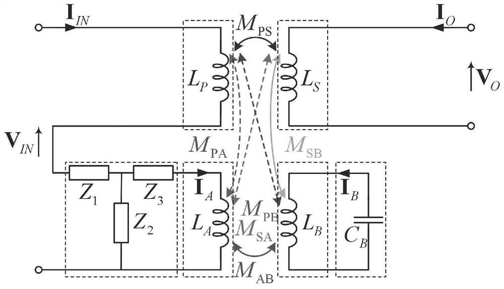
[0062] A hybrid IPT coupler with high offset resistance, such as figure 1 As shown, the coupler consists of a primary coil L P , primary additional coil L A , secondary coil L S , Secondary additional coil L B , primary side T-type compensation network and secondary side compensation capacitor C B .

[0063] Primary coil L P The positive pole of the hybrid IPT coupler is the primary input positive pole, and the primary coil L P The negative pole of the prima...


PUM


Abstract

The invention discloses a hybrid IPT coupler with a high anti-offset characteristic. The hybrid IPT coupler comprises a primary side coil LP, a primary side additional coil LA, a secondary side coil LS, a secondary side additional coil LB, a primary side T-type compensation network and a secondary side compensation capacitor CB, and is characterized in that a positive electrode of the primary side coil LP is a primary side input positive electrode of the hybrid IPT coupler; the negative electrode of the primary side coil LP is connected with the positive electrode of the input end of the primary side T-type compensation network, the negative electrode of the input end of the primary side T-type compensation network is the primary side input negative electrode of the hybrid IPT coupler, the output end of the primary side T-type compensation network is connected to the primary side additional coil LA in parallel, the secondary side compensation capacitor CB is connected to the secondary side additional coil LB in parallel, and two ends of the secondary side coil LS are secondary side output ports of the hybrid IPT coupler. According to the hybrid IPT coupler, polarity requirements of MPS, MAB and MSB are met by designing the primary side T-type compensation network structure, the requirement for BP pad coil mutual inductance parameter design is not high, and equivalent self-inductance and small mutual inductance coefficient fluctuation of the coupler can be achieved under large offset.

Description

technical field [0001] The invention discloses a hybrid IPT coupler with high anti-offset characteristics, relates to wireless energy transmission technology, and belongs to the technical field of power generation, power transformation or power distribution. Background technique [0002] WPT (Wireless Power Transfer Technology) is easy to use and safe and reliable because there is no electrical and mechanical connection between the power supply end and the power receiving end. Currently, IPT (Inductive Wireless Power Transfer) technology is the most widely used WPT technology. IPT transmits energy through loosely coupled transformers. In some applications, the primary and secondary coils of the IPT converter inevitably shift, thereby changing the mutual inductance coefficient, causing large fluctuations in the output voltage or current, and reducing the transmission power. In order to ensure that the IPT system can output stable power in the case of offset, the existing res...

Claims


Application Information

Patent Timeline
IPC IPC(8): H01F27/28H01F27/42H02J50/10
CPCH01F27/28H01F27/42H02J50/10Y02T90/14
Inventor 曲小慧赵玮
Owner SOUTHEAST UNIV
Why Eureka
Try Eureka