
Relay with high fixing performance

A relay and performance technology, applied in the field of relays with strong fixed performance, can solve the problems of inconvenient installation and fixation of thermal relays, and achieve the effect of ensuring stability

Pending Publication Date: 2021-08-27
杨语昆
View PDF3 Cites 0 Cited by
  • Summary
  • Abstract
  • Description
  • Claims
  • Application Information

AI Technical Summary

Problems solved by technology

[0004] The purpose of this invention is to solve the disadvantage of inconvenient installation and fixation of thermal relays, and propose a relay with strong fixing performance

Method used


Image

  • Relay with high fixing performance
  • Relay with high fixing performance
  • Relay with high fixing performance

Examples


Embodiment 1

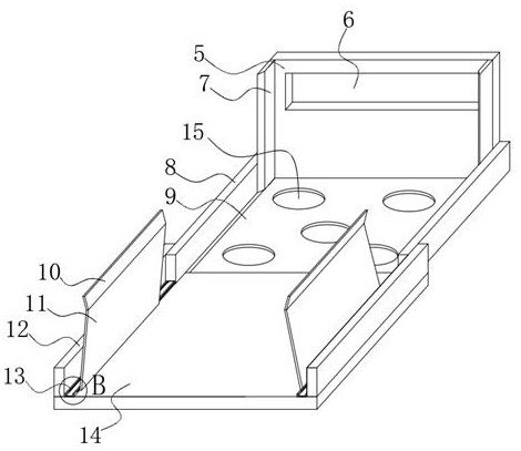
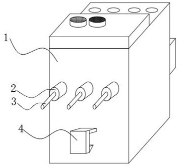
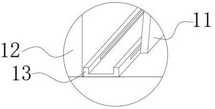
[0031] A relay with strong fixed performance, such as Figure 1-7As shown, it includes a first base plate 9, a relay body 1, and a second base plate 14. The rear end of the top of the first base plate 9 is fixed with a back plate 5 by bolts, and the top of the two ends of the back plate 5 has mounting holes 6. 5 Both sides of the front end are fixed with side plates 7 by screws, the bottoms of both sides of the back plate 5 are fixed with first baffles 8 by bolts, and one side between the two first baffles 8 is connected to two A side plate 7, and there is a gap between the two first baffle plates 8 and the first bottom plate 9, the middle and both sides of the bottom of the two first baffle plates 8 are provided with rectangular grooves, and the two sides of the rectangular grooves in the middle There are rectangular through-holes on the sides, and a number of rollers 17 are inserted into the two rectangular through-holes, and a turntable 20 is fixedly installed on one end of...

Embodiment 2

[0039] A relay with strong fixed performance, such as Figure 8 As shown, in order to solve the problem of insufficient clamping force of the plastic splint 11; this embodiment makes the following improvements on the basis of Embodiment 1: the middle part of one side between the two second baffles 12 is fixed with bolts. Cylindrical box 24, and two cylindrical boxes 24 have circular openings on the side away from the second baffle plate 12, and the sides of the two cylindrical boxes 24 circular openings away from the swash plate 10 are all fixed First gaskets 25 are installed, and springs 26 are fixedly installed on the sides of the two first gaskets 25 away from the second baffle plate 12 .

[0040] In the present invention, the ends of the two springs 26 away from the first gasket 25 are fixedly installed with the second gasket 27 , and the sides of the two second gaskets 27 away from the second baffle 12 are connected to the plastic splint 11 .

[0041] When the present em...


PUM


Abstract

The invention discloses a relay with high fixing performance, relates to the technical field of relays, and is to solve the problem that a thermal relay is difficult to install and fix. The relay specifically comprises a first bottom plate, a relay body and a second bottom plate; a back plate is fixedly mounted at the rear end of the top of the first bottom plate through bolts; mounting holes are formed in the tops of the two ends of the back plate; side plates are fixedly mounted on the two sides of the front end of the back plate through screws; first baffles are fixedly mounted at the bottoms of the two sides of the back plate through bolts; and one side between the two first baffles is connected to the two side plates. According to the device, the sliding rail, the rolling wheels, the second bottom plate and other devices are arranged, the first baffles are used for fixing the rolling shafts and the rolling wheels,and the purpose that the first baffles slide on the surface of the sliding rail is achieved; and meanwhile, the concave hole is formed in the back face of the second bottom plate, and when the thermal relay is installed, the pure copper pins are pushed to be inserted into the receiving relay, the screw is screwed tightly, so that the installation is convenient, and the stability of the relay is ensured.

Description

technical field [0001] The invention relates to the technical field of relays, in particular to a relay with strong fixing performance. Background technique [0002] The relay is an electric control device, which is an electrical appliance that causes the controlled quantity to undergo a predetermined step change in the electrical output circuit when the change of the input quantity (excitation quantity) meets the specified requirements. It has an interactive relationship between the control system (also known as the input loop) and the controlled system (also known as the output loop). Usually used in automatic control circuits, it is actually an "automatic switch" that uses a small current to control the operation of a large current. Therefore, it plays the role of automatic adjustment, safety protection, conversion circuit, etc. in the circuit. The relay is an automatic switching element with isolation function. It is widely used in remote control, telemetry, communicati...

Claims


Application Information

Patent Timeline
IPC IPC(8): H01H45/04H01H45/14
CPCH01H45/04H01H45/14
Inventor 杨语昆
Owner 杨语昆
Learn More