
Cable connector

A technology of cable connectors and limit sleeves, which is applied in the direction of connection, multi-core cable end parts, and parts of connection devices, etc., which can solve the problem of inability to realize quick assembly and quick disassembly, increase connector assembly time, increase cost, etc. problems, to achieve the effect of ensuring firmness and stability, ensuring firmness, and facilitating installation and disassembly

Pending Publication Date: 2021-08-27
太仓泰柯尼电缆有限公司
View PDF0 Cites 1 Cited by
  • Summary
  • Abstract
  • Description
  • Claims
  • Application Information

AI Technical Summary

Problems solved by technology

Unable to achieve quick installation and quick release
Moreover, under normal circumstances, different manufacturers need to perform laser coding on the surface of the connector, and spray their own logo on the surface, which will also increase the assembly time of the connector and increase the cost.

Method used


Image

  • Cable connector
  • Cable connector
  • Cable connector

Examples


Embodiment 1

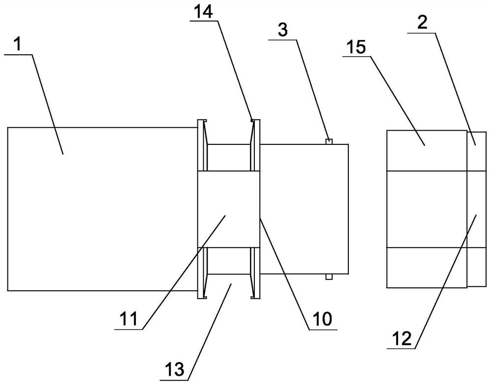
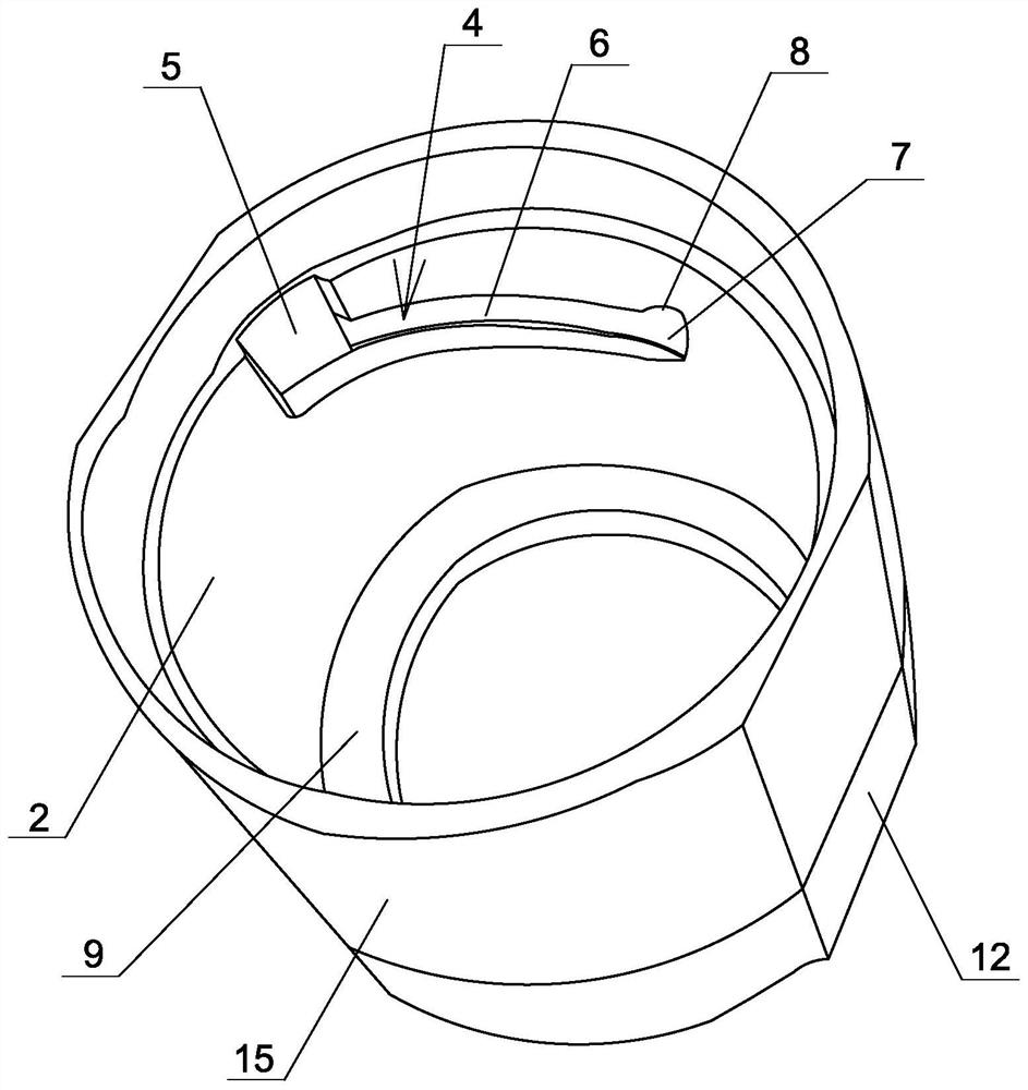
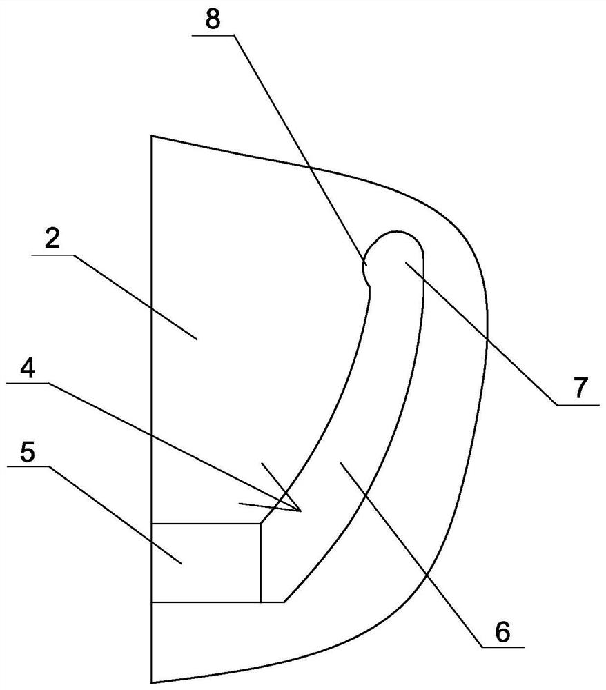
[0022] Embodiment one: see Figure 1~3 As shown, a cable connector includes a body 1, the right end of the body is provided with a limit sleeve 2 for limiting the cable, the left end of the body is provided with a plug-in terminal, and the outer edge surface of the right end of the body There are two groups of limiting protrusions 3 arranged symmetrically on the top, and two groups of limiting grooves 4 are symmetrically arranged on the inner wall of the limiting sleeve. The front ends of the limiting grooves communicate with the left side of the limiting sleeve. The limit sleeve is inserted on the right end of the body, each set of limit protrusions is inserted into a set of limit slots, and the limit sleeve is rotated to lock the limit protrusions Located at the right end of the limiting groove, the limiting protrusion and the limiting groove lock and connect the body and the limiting sleeve.

[0023] In this embodiment, a screw sleeve is provided on the left side of the bo...


PUM


Abstract

The invention discloses a cable connector which comprises a body; a limiting sleeve for limiting a cable is arranged at the right end of the body; and a plugging terminal is arranged in the left end of the body. The cable connector is characterized in that two sets of limiting protrusions are symmetrically arranged on the outer edge face of the right end of the body, and two sets of limiting grooves are symmetrically formed in the inner wall of the limiting sleeve; the front ends of the limiting grooves are communicated with the left side face of the limiting sleeve; the limiting sleeve is inserted into the right end of the body; each set of limiting protrusions are inserted into one set of limiting grooves; by rotating the limiting sleeve, the limiting protrusions are clamped at the right ends of the limiting grooves, and the body and the limiting sleeve are connected in a locked mode through the limiting protrusions and the limiting grooves. According to the invention, quick assembly and quick disassembly of the connector are realized.

Description

technical field [0001] The invention relates to a connector, in particular to a cable connector. Background technique [0002] Cable connectors are mainly used for power transmission and signal transmission between equipment and power supply, equipment and equipment. For example, when the motor is connected to the control box or power supply, it is connected with a cable to realize the transmission connection of power supply and data. Generally, when the cable harness is connected to the connector, the end of the cable harness is screwed and locked on the connector by using a nut. In this assembly method, the assembly force must be particularly large, and the screw connection speed is relatively slow. Quick assembly and quick release cannot be realized. Moreover, under normal circumstances, different manufacturers need to perform laser coding on the surface of the connector, and spray their own logo on the surface, which will also increase the assembly time of the connect...

Claims


Application Information

Patent Timeline
Patent Type & Authority Applications(China)
IPC IPC(8): H01R13/502H01R13/639H01R11/11
CPCH01R11/11H01R13/502H01R13/639
Inventor 高飞李虎尹伟杰
Owner 太仓泰柯尼电缆有限公司
Learn More