Full-automatic intelligent ball valve production line

A fully automatic, production line technology, applied in the direction of cleaning methods, sorting, cleaning methods and utensils using gas flow, which can solve the problems of easy flow into the production line, inconvenient and timely separation of good and bad products, and low efficiency

Active Publication Date: 2021-08-31
安徽齐力不锈钢制品有限公司
View PDF7 Cites 0 Cited by
  • Summary
  • Abstract
  • Description
  • Claims
  • Application Information

AI Technical Summary

Problems solved by technology

[0004]1. As most of the assembly is done by hand, there are shortcomings brought about by hand, the quality of assembly is different, and the efficiency is low
[0005]2. Due to the air tightness test of the finished product and the testing of the workpiece du...

Method used


Image

  • Full-automatic intelligent ball valve production line
  • Full-automatic intelligent ball valve production line
  • Full-automatic intelligent ball valve production line

Examples


Embodiment 1

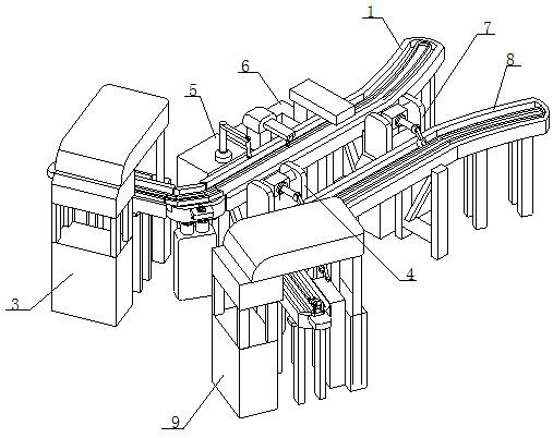
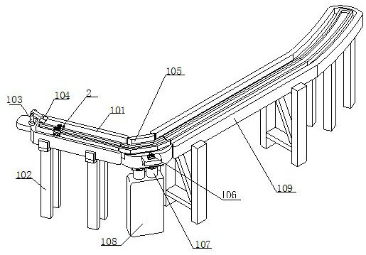
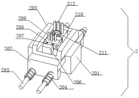
[0031] see Figure 1-3, the present invention provides a technical solution: a fully automatic intelligent ball valve production line, a valve seat feeding device 1, a delivery fixture 2 is installed on the inside of the valve seat feeding device 1, and a valve seat assembly device 3 is installed on one end of the valve seat feeding device 1. , the external movement of the valve seat feeding device 1 is equipped with a turning device-4, and the end of the valve seat feeding device 1 away from the turning device-4 is movably installed with a ball valve side screw cap installation device 5, and the ball valve side screw cap installation device 5 is assembled away from the valve seat One end of the device 3 is movably equipped with an airtightness detection device 6, and the end of the valve seat feeding device 1 away from the airtightness detection device 6 is movably installed with an overturning device 2 7; The bottom of the track one 101 is fixedly equipped with a bracket 102...

Embodiment 2

[0034] see Figure 4-7 As shown, on the basis of Embodiment 1, the present invention provides a technical solution: the interior of the valve seat assembly device 3 includes a fixed platform 301, and the top of the fixed platform 301 is movably installed with an installation crank arm 302, and the installation crank arm 302 is away from the fixed One end of table 301 is fixedly installed with mounting head 303, and one end of fixed table 301 is fixedly connected with supporting machine table 304; The inside of flipping device-4 includes turning machine table 401, and the top of turning machine table 401 is fixedly installed with side plate 402, and the side The inner wall of the plate 402 is movably equipped with a connecting shaft 403, and the outer wall of the connecting shaft 403 is fixedly equipped with a turning block 404, and the outer wall of the turning block 404 is movable, and the rotating arm 405 is movable, and the end of the turning arm 405 far away from the turnin...


PUM


Abstract

The invention discloses a full-automatic intelligent ball valve production line, which comprises a valve seat feeding device, wherein a conveying clamp is movably installed in the valve seat feeding device; a valve seat assembling device is movably installed at one end of the valve seat feeding device; an overturning device I is movably installed outside the valve seat feeding device; a ball valve side blind nut mounting device is movably installed at the end, away from the overturning device I, of the valve seat feeding device; an airtightness detection device is movably installed at the end, away from the valve seat assembling device, of the ball valve side blind nut mounting device; an overturning device II is movably installed at the end, away from the airtightness detection device, of the valve seat feeding device; and a conveying rail I is arranged inside the valve seat feeding device. The conveying clamp can be conveyed to a ball valve machining position through the arranged valve seat feeding device, automation is achieved, the airtightness of workpieces can be detected through the airtightness detection device, and good products and defective products are separated through the overturning device II.

Description

technical field [0001] The invention belongs to the technical field of ball valve production, and in particular relates to a fully automatic intelligent ball valve production line. Background technique [0002] Ball valve, the opening and closing part (ball) is driven by the valve stem and rotates around the axis of the ball valve. It can also be used for the regulation and control of fluids, among which the hard-sealed V-shaped ball valve has a strong shear force between its V-shaped ball core and the metal valve seat of surfacing welding carbide, especially suitable for fibers, tiny solid particles, etc. medium. The multi-way ball valve can not only flexibly control the confluence, diversion, and flow direction switching of the medium on the pipeline, but also close any channel and connect the other two channels. This type of valve should generally be installed horizontally in the pipeline. According to the driving mode, the ball valve is divided into: pneumatic ball va...

Claims


Application Information

Patent Timeline
IPC IPC(8): B07C5/02B07C5/34B07C5/36B08B5/02B65G47/91
CPCB07C5/02B07C5/3404B07C5/3416B07C5/362B08B5/023B65G47/915B07C2501/0063
Inventor 朱常有张继陈海兵张超
Owner 安徽齐力不锈钢制品有限公司
Why Eureka
Try Eureka