
A split air path structure for metal 3D printing equipment

A 3D printing and equipment technology, applied in the field of split air path structure, can solve the problems of laser intensity reduction, uneven sintering, workpiece precision and strength defects, etc., to achieve the effect of ensuring processing quality, high decontamination efficiency, and good protection effect

Active Publication Date: 2022-03-08
JIHUA LAB
View PDF0 Cites 0 Cited by
  • Summary
  • Abstract
  • Description
  • Claims
  • Application Information

AI Technical Summary

Problems solved by technology

If these particles are attached to the powder bed, the next layer of powder cannot be completely fused and sintered, which will affect the strength of the molded workpiece. If these particles are attached to the galvanometer protective mirror, it will affect the entire laser system, resulting in a decrease in laser intensity, resulting in Uneven or incomplete sintering, which eventually leads to serious defects in the accuracy and strength of the workpiece

Method used


Image

  • A split air path structure for metal 3D printing equipment
  • A split air path structure for metal 3D printing equipment
  • A split air path structure for metal 3D printing equipment

Examples


Embodiment Construction

[0025] Embodiments of the present invention are described in detail below, examples of which are shown in the drawings, wherein the same or similar reference numerals denote the same or similar elements or elements having the same or similar functions throughout. The embodiments described below by referring to the figures are exemplary only for explaining the present invention and should not be construed as limiting the present invention.

[0026] In describing the present invention, it should be understood that the terms "center", "longitudinal", "transverse", "length", "width", "thickness", "upper", "lower", "front", " Orientation indicated by rear, left, right, vertical, horizontal, top, bottom, inside, outside, clockwise, counterclockwise, etc. The positional relationship is based on the orientation or positional relationship shown in the drawings, which is only for the convenience of describing the present invention and simplifying the description, rather than indicating ...


PUM


Abstract

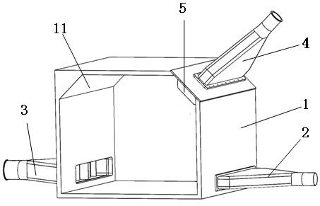
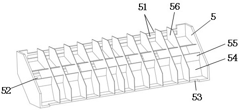
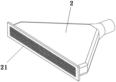
The invention discloses a split air path structure for metal 3D printing equipment, which includes a printing chamber body, an air inlet and an air outlet respectively arranged on both sides of the printing chamber body, and also includes a split air member. Set on one side of the top of the printing silo body, it is used to supply air from the top of the printing silo body to the printing silo body, the air outlet end is divided into a shunt, and the shunt is provided with a deflector; the present application is used for metal 3D printing. For the split air path structure of the equipment, by adding a split air piece on the top side of the printing box body, and by setting a deflector in the splitter, the air intake of the split wind piece is divided into three directions of air supply, which effectively removes the The pollutants generated in the printing chamber during the 3D printing process form a protective layer for protecting the galvanometer area and components, thereby effectively ensuring the quality of 3D printing processing. It has the characteristics of simple structure, good protection effect and high decontamination efficiency.

Description

technical field [0001] The invention belongs to the technical field of metal forming, and in particular relates to a split air path structure for metal 3D printing equipment. Background technique [0002] Metal additive manufacturing mainly realizes 3D printing through laser sintering (SLS) or laser melting powder bed specific powder (SLM). The laser provides an energy source to melt and sinter the powder bed, and then repeat the above steps for layer-by-layer molding to manufacture the target object layer by layer. [0003] In traditional metal 3D printing equipment, it is usually divided into powder feeding device, powder spreading device, forming platform and residual powder collecting device, etc. The current SLM metal additive manufacturing equipment needs to deflect the laser through optical elements such as galvanometers, so as to control The powder in a specific printing area is melted; however, during the molding process, due to the interaction between the laser an...

Claims


Application Information

Patent Timeline
Patent Type & Authority Patents(China)
IPC IPC(8): B22F12/70B33Y30/00
CPCB22F12/70B33Y30/00Y02P10/25
Inventor 侯志轩张士亨何刚文赵豪李建杰王冠博
Owner JIHUA LAB
Learn More