Device and method for reducing machining deformation of heat exchange fin

A technology for processing deformation and heat exchange fins, applied in positioning devices, metal processing equipment, metal processing machinery parts, etc., can solve the problems of easy deformation of heat transfer fins, achieve the effects of reducing processing deformation, improving work efficiency, and saving costs

Pending Publication Date: 2021-08-31
航天科工哈尔滨风华有限公司
View PDF0 Cites 0 Cited by
  • Summary
  • Abstract
  • Description
  • Claims
  • Application Information

AI Technical Summary

Problems solved by technology

[0003] In order to solve the problem that heat exchange fins are easily deformed during clamping and processing in the prior art, the present invention provides a device and method for reducing processing deformation of heat exchange fins

Method used


Image

  • Device and method for reducing machining deformation of heat exchange fin
  • Device and method for reducing machining deformation of heat exchange fin
  • Device and method for reducing machining deformation of heat exchange fin

Examples


Embodiment 1

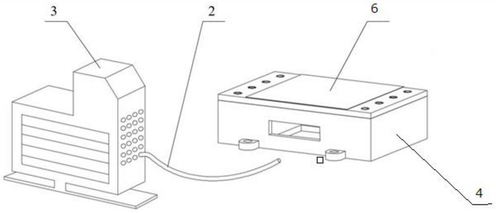
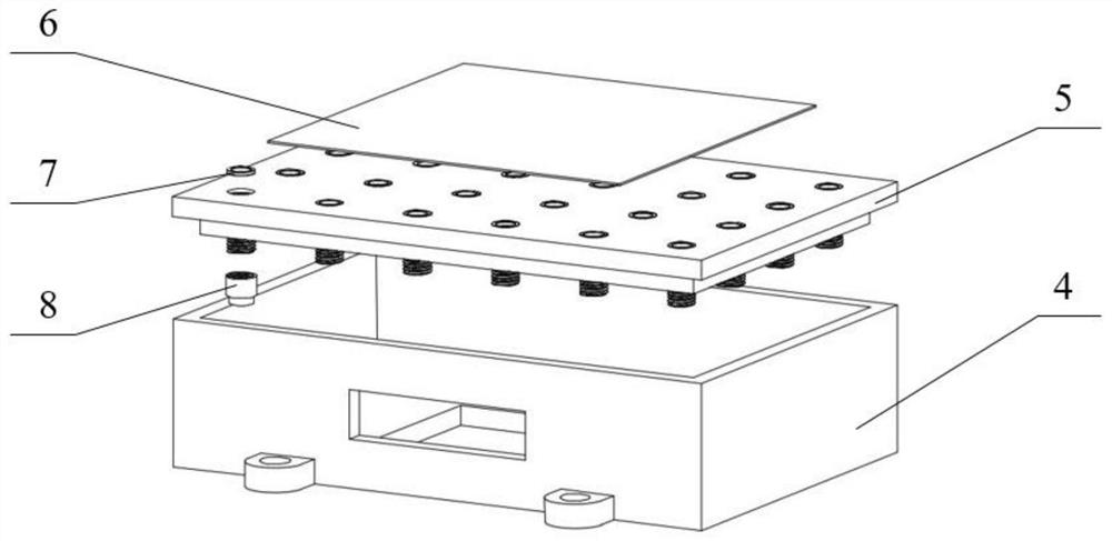
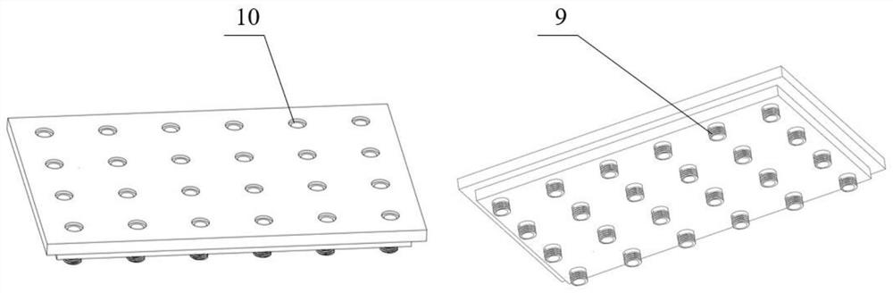
[0046] A device for reducing processing deformation of heat exchange fins, the device includes a base 4, a support plate 5, and a vacuum pump, the base is rectangular, the support plate 5 is arranged above the base 4, and 60 pipes are arranged on the support plate 5 10. The pipeline 10 is a circular pipeline, one end of the pipeline 10 is flush with the surface of the support plate 5 , and the other end is sealed and connected with the vacuum device 3 . The material of the base 4 is No. 45 steel with good comprehensive mechanical properties, and the material of the support plate 5 is aluminum alloy. The heat exchange fin blanks 6 are placed above the pipes 10 on the support plate 5 and cover the upper openings of 20 pipes 10 , that is, the pipes 10 covered by the heat exchange fin blanks 6 are connected to the vacuum pump 3 .

Embodiment 2

[0048]On the basis of Embodiment 1, the pipeline 10 is airtightly connected with the vacuum pump 3 through the vacuum hose 2 . The pipeline 10 is connected to the vacuum hose 2 through a hose connection sleeve 8, the hose connection sleeve 8 is a stepped sleeve, the large-diameter end of the hose connection sleeve is connected to the pipeline thread, and the small-diameter end is connected to the pumping hose 2. Vacuum hose socket. The side wall of the base 4 is provided with a hose outlet, and the vacuum hose 2 passes through the hose outlet 15 and is connected to the pipeline 10 .

[0049] The support plate 5 is adapted to the size of the base 4 and is inlaid and sealed. A sealing ring 7 matching the caliber of the pipeline 10 is provided at the opening above the pipeline 10. A cooling liquid storage tank 13 is provided at the bottom of the base 4. The cooling liquid containing groove 13 is arranged below the heat exchange fin blank.

[0050] In another aspect, the present...


PUM


Abstract

The invention relates to the field of heat exchangers, and discloses a device and method for reducing machining deformation of a heat exchange fin. The device comprises a base, a supporting plate and a vacuumizing device, wherein the supporting plate is arranged above the base, and a plurality of pipelines are arranged on the supporting plate; one end of each pipeline is flush with the plate face of the supporting plate, and the other end of each pipeline extends out of the supporting plate and is hermetically connected with the vacuumizing device. The method comprises the following steps of: (1) conducting finishing treatment on a heat exchange fin blank before machining; (2) mounting the device for reducing machining deformation of the heat exchange fin, placing the heat exchange fin blank on the supporting plate, connecting the pipelines to the vacuumizing device, and starting the vacuumizing device; (3) conducting milling machining of pouring cooling liquid on the heat exchange fin blank; and (4) after milling is completed, closing the vacuumizing device, conducting vacuum breaking, and taking down the part. The device solves the problem that the heat exchange fin is very easy to deform during clamping and machining is effectively solved, and has the advantages of being easy to operate and low in cost.

Description

technical field [0001] The invention belongs to the field of heat exchangers, and more specifically relates to a device and method for reducing processing deformation of heat exchange fins. Background technique [0002] As the main component of the plate-plate heat exchanger, the heat exchange fin has high heat exchange efficiency, small footprint, multiple forms, flexible assembly, convenient disassembly, cleaning and maintenance, and is widely used in various industries such as electric power, petroleum, chemical industry, air conditioning, etc. . However, since it is a thin-walled part, mostly made of aluminum alloy, it is easily deformed during clamping and processing, resulting in a high reject rate during processing, which brings great difficulties to manufacturing. With the continuous improvement of processing requirements, it is difficult for the existing clamping tools to meet the processing requirements, and most of the processing methods used to reduce the deform...

Claims


Application Information

Patent Timeline
Patent Type & Authority Applications(China)
IPC IPC(8): B23Q3/08B23P15/00
CPCB23Q3/088B23P15/00
Inventor 李震豪翟学智魏士亮戴占洋
Owner 航天科工哈尔滨风华有限公司
Why Eureka
Try Eureka