Machine tool lead screw pre-stretching installation mechanism

A mounting mechanism and pre-stretching technology, which is applied in the direction of feeding device, maintenance and safety accessories, metal processing machinery parts, etc., can solve the problem that the service life cannot meet the design requirements, lubricating oil leakage, oil seal seals and screw rod seals Easy to produce gaps and other problems

Active Publication Date: 2021-08-31
XIAMEN TAKAM MACHINERY
View PDF9 Cites 0 Cited by
  • Summary
  • Abstract
  • Description
  • Claims
  • Application Information

AI Technical Summary

Problems solved by technology

[0004] 1) The oil seals located at the front and rear ends of the mounting seat are in line contact with the mounting end of the screw for sealing. Since the screw rotates frequently during the machining process of the machine tool, the wear of the oil seal by the screw is relatively large, resulting in The seal between the oil seal and the screw rod is prone to gaps, which will lead to leakage of lubricating oil, and may cause external coolant or chips to enter the mounting seat, which will damage the installation stability of the screw rod, resulting in the failure of each component. The service life cannot meet the design requirements;
[0005] 2) The anti-collision buffer block installed on the rear end surface of the mounting seat is mainly made of rubber block with cushioning effect. Although it has a certain buffering effect, its energy dissipation effect is poor. Once an impact occurs, the damage of the mounting seat is extremely difficult. be effectively controlled

Method used


Image

  • Machine tool lead screw pre-stretching installation mechanism
  • Machine tool lead screw pre-stretching installation mechanism
  • Machine tool lead screw pre-stretching installation mechanism

Examples


Embodiment Construction

[0032] In order to facilitate the understanding of those skilled in the art, the structure of the present invention will be further described in detail with the embodiments in conjunction with the accompanying drawings:

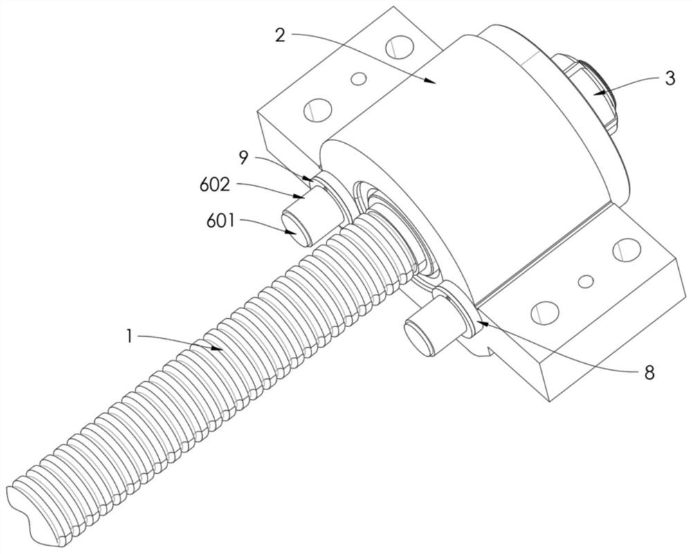
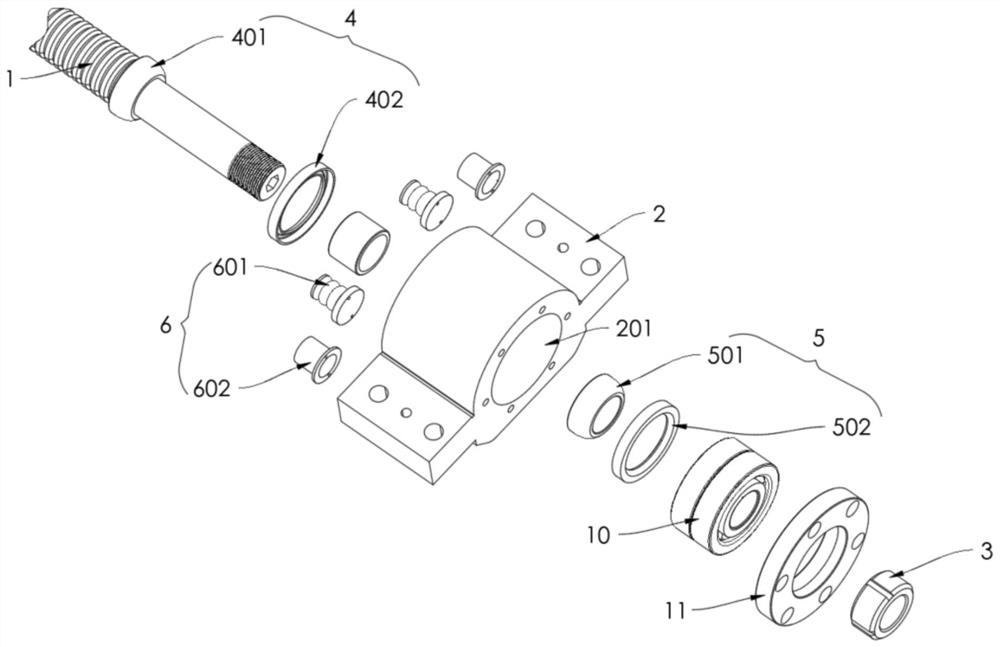
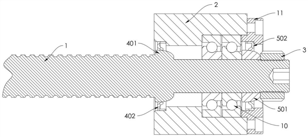
[0033] refer to Figure 1-7 , a screw pre-stretching installation mechanism for a machine tool, comprising a screw 1, a mounting base 2 with a mounting hole 201, the mounting end of the screw 1 is rotatably installed in the mounting hole 201, the front end of the screw 1 A lock nut 3 that can pre-stretch the screw rod 1 is connected through a threaded connection; it also includes

[0034] The first sealing mechanism 4 includes a fixed ring 401 fixedly connected to the rear side of the installation end of the screw rod 1. The outer wall of the fixed ring 401 is in the shape of an arc with a narrow front and a wide rear. A first gasket 402 is installed between the installation hole 201 of the installation seat 2, and the first sealing gasket 402 includes a fir...


PUM


Abstract

The invention relates to a machine tool lead screw pre-stretching installation mechanism. The machine tool lead screw pre-stretching installation mechanism comprises a lead screw and an installation base with an installation hole, wherein the installation end of the lead screw is rotationally installed in the installation hole, the front end of the lead screw is connected to a locking nut capable of pre-stretching the lead screw in a threaded connection mode, the machine tool lead screw pre-stretching installation mechanism further comprises a first sealing mechanism and a second sealing mechanism, wherein the first sealing mechanism comprises a fixing ring sleeve fixedly connected to the rear side of the installing end of the lead screw, the outer side wall of the fixing ring sleeve is in an arc shape with the front portion narrow and the rear portion wide, a first sealing gasket is arranged between the outer side wall of the fixing ring sleeve and the installing hole of the installing base, the second sealing mechanism comprises a movable ring sleeve fixedly connected to the rear side of the locking nut in a sleeve mode, the outer side wall of the movable ring sleeve is in an arc shape with the front portion narrow and the rear portion wide, and a second sealing gasket is arranged between the outer side wall of the movable ring sleeve and the installing hole of the installing base. According to the machine tool lead screw pre-stretching installation mechanism, on the basis that normal prestretching installation does not affect, the sealing effect of the front end and the rear end of the installation base can be effectively and greatly improved.

Description

technical field [0001] The invention relates to a pre-stretching installation mechanism of a screw rod of a machine tool, which is mainly used for pre-stretching installation of the screw rod of a machine tool. Background technique [0002] In the feed transmission system of the machine tool, the screw rod is often used as the transmission element to convert the rotary motion of the servo motor into the linear movement of the motion actuator (knife holder or workbench, etc.), and the screw rod is mainly pre-stretched by the screw rod The mounting device is turned and mounted in a pre-tensioned state. [0003] The existing machine tool screw pretensioning installation mechanism has the following defects in actual use: [0004] 1) The oil seals located at the front and rear ends of the mounting seat are in line contact with the mounting end of the screw for sealing. Since the screw rotates frequently during the machining process of the machine tool, the wear of the oil seal b...

Claims


Application Information

Patent Timeline
Patent Type & Authority Applications(China)
IPC IPC(8): B23Q5/40B23Q11/00
CPCB23Q5/40B23Q11/0032
Inventor 林清年
Owner XIAMEN TAKAM MACHINERY
Why Eureka
Try Eureka