Outer R cutter grinding machine tool
A tool grinding and machine tool technology, which is applied in the direction of grinding machine parts, grinding machines, grinding racks, etc., can solve the problems of low fillet accuracy and slow tool connection, and achieve the effect of high position accuracy
- Summary
- Abstract
- Description
- Claims
- Application Information
AI Technical Summary
Problems solved by technology
Method used
Image
Examples
Embodiment 1
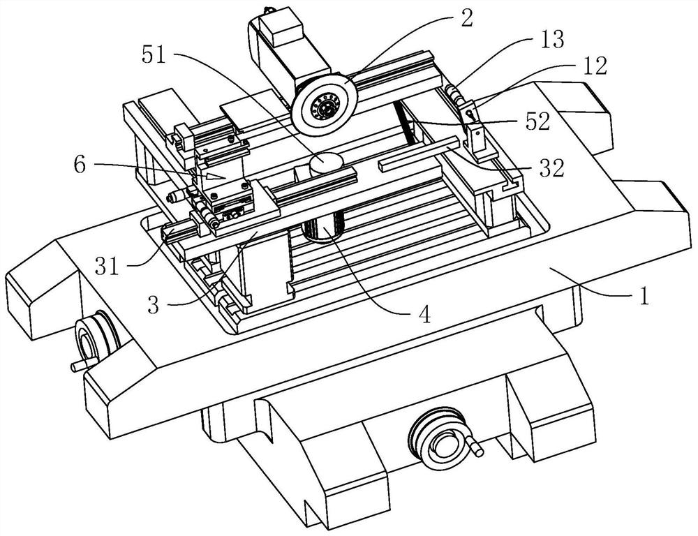
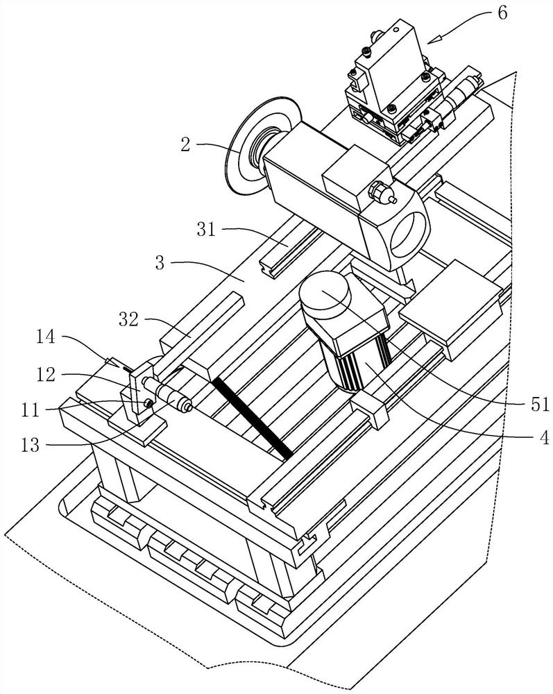
[0040] Embodiment 1, with reference to figure 1 , the outer R tool grinding machine includes a frame 1, a grinding disc 2 and a rotating plate 3, the grinding disc 2 is rotatably set on the frame 1, and the axis of the grinding disc 2 is perpendicular to the horizontal plane, and a servo motor is installed on the frame 1 to Make the grinding disc 2 rotate around its own axis; the rotating plate 3 is horizontally arranged on the frame 1, and one end of the rotating plate 3 is rotatably connected with the frame 1, and the upper surface of the rotating plate 3 is also equipped with a tool for holding the tool. Fixture 6, then just can make rotating plate 3 do swinging motion around the junction of itself and frame 1, so that cutter contacts with grinding disc 2 under the rotating state, thereby can process the fillet on cutter.
[0041] refer to figure 1 , the frame 1 is also fixedly provided with a drive motor 4, and the output shaft of the drive motor 4 is perpendicular to the...
Embodiment 2
[0054] Embodiment 2, with reference to figure 1 with Figure 4 , the difference from Embodiment 1 is that the transmission member 5 includes a drive rod 53 and a driven rod 54, one end of the drive rod 53 is fixedly connected to the output shaft of the drive motor 4, and the axis of the drive rod 53 is connected to the output of the drive motor 4 The shaft is vertical; one end of the driven rod 54 is hinged on the end of the drive rod 53 away from the output shaft of the drive motor 4, and the other end is hinged with the rotating plate 3, then when the drive motor 4 starts, the drive rod 53 and the driven rod 54 will be A crank linkage mechanism is formed, so that the rotating plate 3 can swing around the joint between itself and the frame 1 .
Embodiment 3
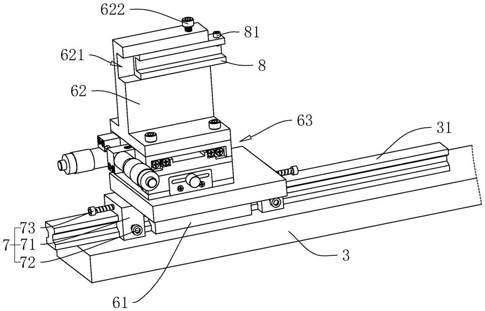
[0055] Embodiment 3, with reference to figure 2 with Figure 5 , the difference from Embodiment 1 is that a chute 82 is provided on the outer wall of the U-shaped block 8 close to the third locking rod 622, and the section at the notch of the chute 82 is rectangular, and the length direction of the chute 82 is parallel In the direction of communication with the clamping channel 621, in this embodiment, the end of the third locking rod 622 close to the chute 82 is threaded with a limit block 623, the limit block 623 is in the shape of a positive prism, and acts as a U-shaped block 8 is locked, the limit block 623 will abut against the inner wall of the chute 82 and the clamping channel 621, then when the tool is subjected to external force during processing, the U-shaped block 8 is not easy to rotate, so that it can be further improved Stability of the tool in the process.
PUM
 Abstract
Description
Claims
Application Information
 - R&D
- Intellectual Property
- Life Sciences
- Materials
- Tech Scout
- Unparalleled Data Quality
- Higher Quality Content
- 60% Fewer Hallucinations
Browse by: Latest US Patents, China's latest patents, Technical Efficacy Thesaurus, Application Domain, Technology Topic, Popular Technical Reports.
© 2025 PatSnap. All rights reserved.Legal|Privacy policy|Modern Slavery Act Transparency Statement|Sitemap|About US| Contact US: help@patsnap.com


