
Compound machine winding device

A technology of a rewinding device and a compound machine, applied in the field of compound machines, can solve the problems of affecting the efficiency of rewinding, low degree of automation, etc.

Active Publication Date: 2021-08-31
WENZHOU WINRICH MACHINERY CO LTD
View PDF9 Cites 5 Cited by
  • Summary
  • Abstract
  • Description
  • Claims
  • Application Information

AI Technical Summary

Problems solved by technology

[0005] Aiming at the above-mentioned shortcomings existing in the prior art, the present invention provides a compound machine winding device, which can effectively solve the problem that the prior art requires manual operation of the inflatable shaft and the safety chuck, and the degree of automation is low, which affects the overall winding. efficiency problem

Method used

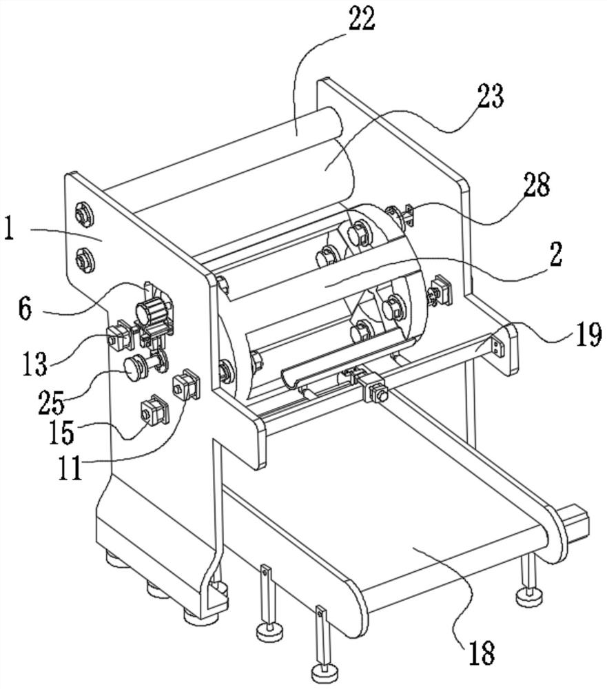
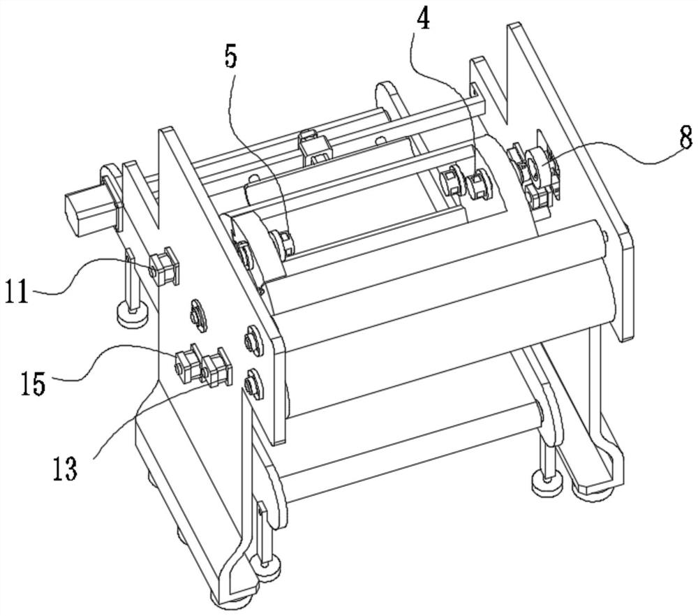
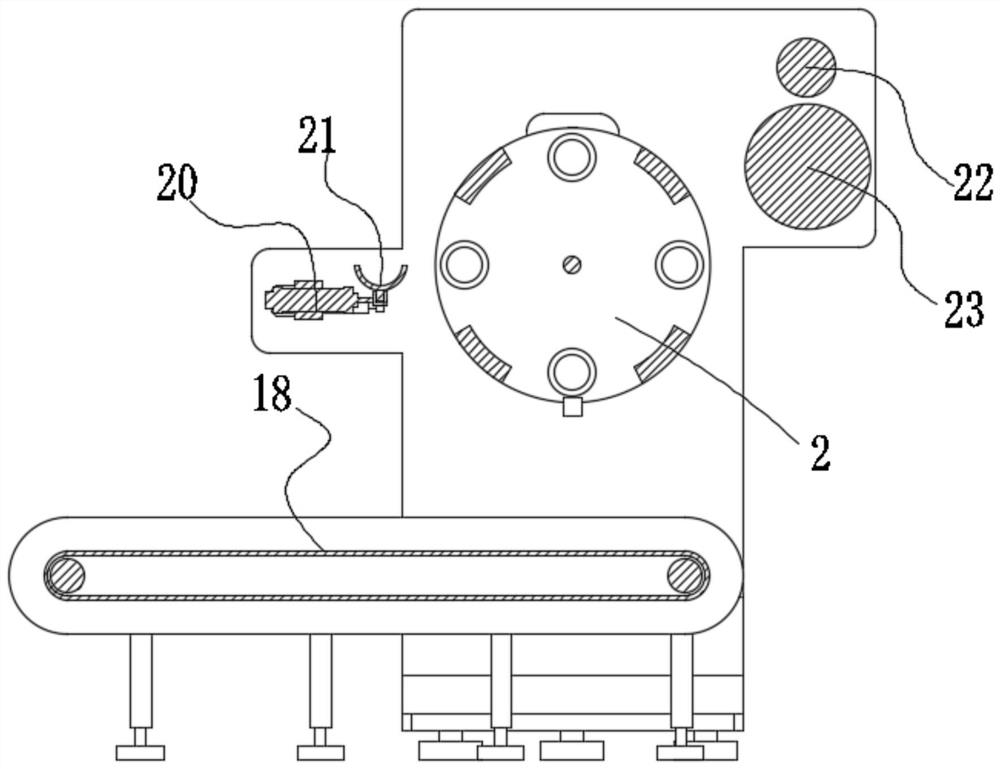

Image

  • Compound machine winding device
  • Compound machine winding device
  • Compound machine winding device

Examples


Embodiment

[0035] A compound machine winding device of this embodiment, refer to Figure 1-9 : the body 1 includes a left plate and a left plate, and the left plate and the left plate are fixed to each other by a crossbeam 19, and in the middle upper area of ​​the left plate (such as figure 1 ) is provided with a port 6 for the first driver to pass through and penetrate into the left plate. The middle part of the body 1 is rotatably connected to the transfer part 2, and the middle part of the transfer part 2 is fixed with a shaft 24 coaxial with it. The left plate and the left plate The middle part is equipped with a bearing that is rotatably matched with the shaft rod 24, so that the transfer member 2 is rotatably connected between the left plate and the left plate, and the transfer member 2 is driven to rotate 90° each time through the second driving mechanism;

[0036] Specifically, the second driving mechanism includes a servo motor and a driving pulley arranged at the output end of ...


PUM


Abstract

The invention relates to the technical field of compound machines, in particular to a compound machine winding device which comprises a machine body, wherein a transfer part is rotationally connected into the middle of the machine body, and four groups of station areas are arranged on the transfer part at equal angles. By controlling the transfer part to rotate by 90 degrees every time, a paper tube on an inflation station is transferred to a winding station, the paper tube wound on the winding station is transferred to a deflation station, the paper tube wound on the deflation station is transferred to an unwinding station, and the empty station area is transferred to the inflation station, so that the paper tube can be clamped. Through cooperation of an inflation mechanism, a first driving mechanism, a deflation mechanism, a roll-down mechanism and a paper tube feeding mechanism, the paper tube is clamped in the inflation station, the paper tube at a roll-up station rotates at a low speed to be rolled up, a left inflatable shaft and a right inflatable shaft at the deflation station are deflated, and the rolled paper tube at the roll-down station is taken down, so that the automation degree is high, operation is easy, consumed time is short, and therefore, the overall winding efficiency is improved.

Description

technical field [0001] The invention relates to the technical field of compound machines, in particular to a compound machine winding device. Background technique [0002] The composite machine is to bond two or more layers of materials into one with an adhesive. In the composite machine, single-station winding is widely used. Usually, a hook is installed on the frame about the width of the frame, and bearings are installed at both ends of the inflatable shaft, and the bearing is placed in the bearing socket on the hook and locked. However, when unwinding after winding, two people are generally required to operate, and the air shaft and the rolled material body need to be removed together. The operation is cumbersome and takes a long time, which affects the overall winding efficiency. [0003] At present, the Chinese patent No. "202011249075.5" discloses a double-station winding device for a compound machine. The left wall panel, the right wall panel and the brackets betwee...

Claims


Application Information

Patent Timeline
Patent Type & Authority Applications(China)
IPC IPC(8): B65H18/04B65H19/26B65H19/30B65H37/04
CPCB65H18/04B65H19/26B65H19/30B65H37/04
Inventor 王龙峰陈好李露瑶
Owner WENZHOU WINRICH MACHINERY CO LTD
Learn More