Constant-speed winding device for optical fiber manufacturing

A winding device and optical fiber technology, which is applied in the field of optical fiber manufacturing, can solve problems affecting production efficiency, economic loss, and fiber breakage, and achieve the effects of improving efficiency, avoiding economic loss, and ensuring uniform winding work

Inactive Publication Date: 2021-08-31
厦门时不待贸易有限公司
View PDF0 Cites 0 Cited by
  • Summary
  • Abstract
  • Description
  • Claims
  • Application Information

AI Technical Summary

Problems solved by technology

[0004] Aiming at the deficiencies of the prior art, the present invention provides a uniform-speed winding device for optical fiber manufacturing, which has the advantages of ensuring constant-speed winding and avoiding fiber breakage, and solves the problem that the existing equipment may cause fiber breakage, which affects production efficiency and brings economic benefits. loss problem

Method used


Image

  • Constant-speed winding device for optical fiber manufacturing
  • Constant-speed winding device for optical fiber manufacturing
  • Constant-speed winding device for optical fiber manufacturing

Examples


Embodiment 1

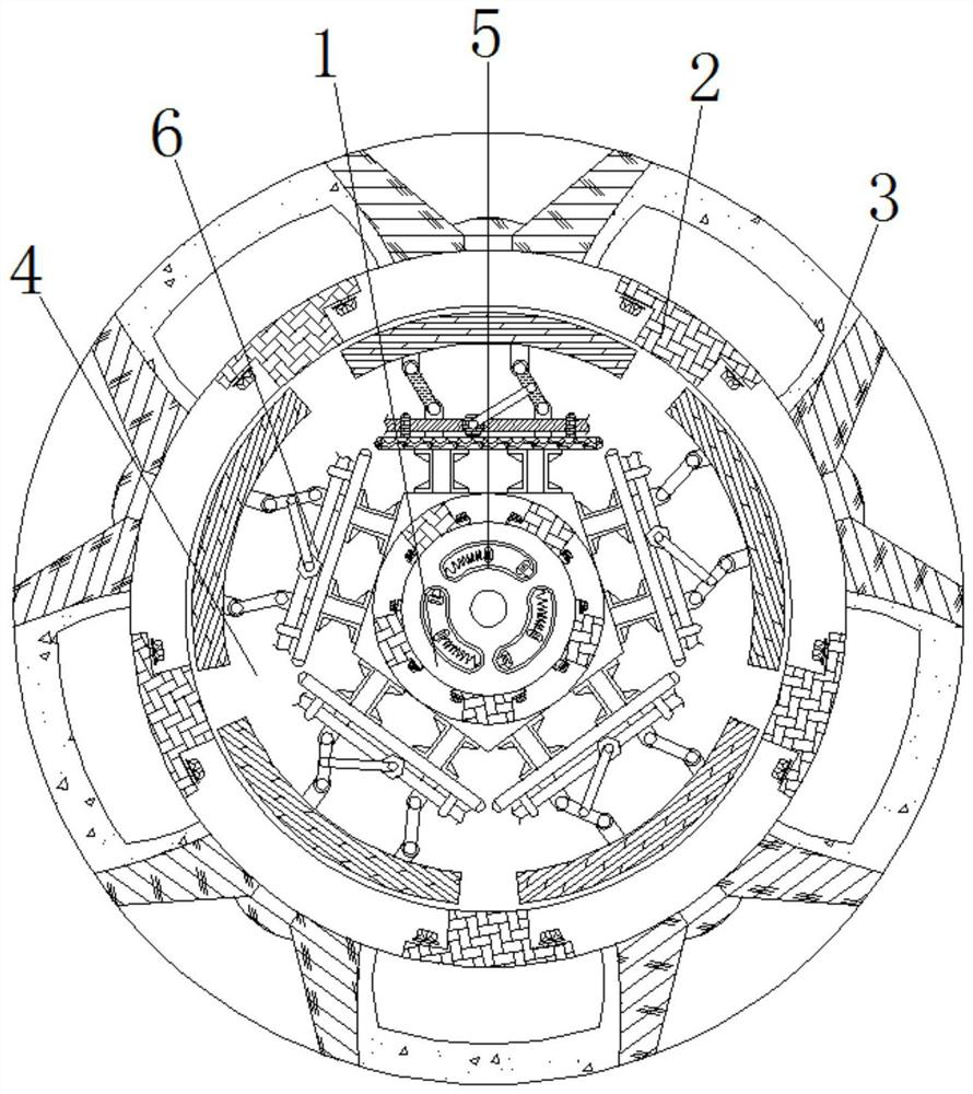
[0024] see figure 1 , figure 2 , Figure 4 , a constant speed winding device for optical fiber manufacturing, comprising a drive disc 1, a connection plate 2 is welded on the outside of the drive disc 1, a locking disc 3 is welded on the outside of the connection plate 2, and a device disc 4 is connected to the front of the drive disc 1 for rotation , the centers of the driving disc 1, the locking disc 3 and the device disc 4 are on the same straight line, and there are five connecting plates 2, which are evenly distributed with the center of the driving disc 1 as the center, and are respectively welded on the periphery of the driving disc 1;

[0025] The diameter of the locking disc 3 is larger than that of the driving disc 1, and the shape of the locking disc 3 is a ring, and five connecting plates 2 are welded between the locking disc 3 and the driving disc 1; the device disc 4 is rotatably connected to the driving disc 1, and the diameter of the device disk 4 is smaller...

Embodiment 2

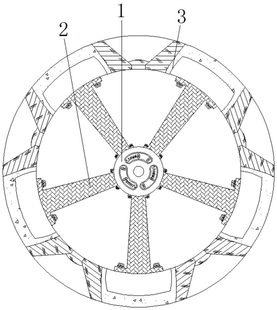
[0028] see figure 1 , figure 2 , image 3 , a constant speed winding device for optical fiber manufacturing, comprising a drive disc 1, characterized in that: the outer side of the drive disc 1 is welded with a connecting plate 2, the outer side of the connecting plate 2 is welded with a locking disc 3, and the front of the drive disc 1 is rotationally connected There is a device disk 4, a trigger mechanism 5 is provided on the front of the drive disk 1, and a locking mechanism 6 is provided on the front of the device disk 4;

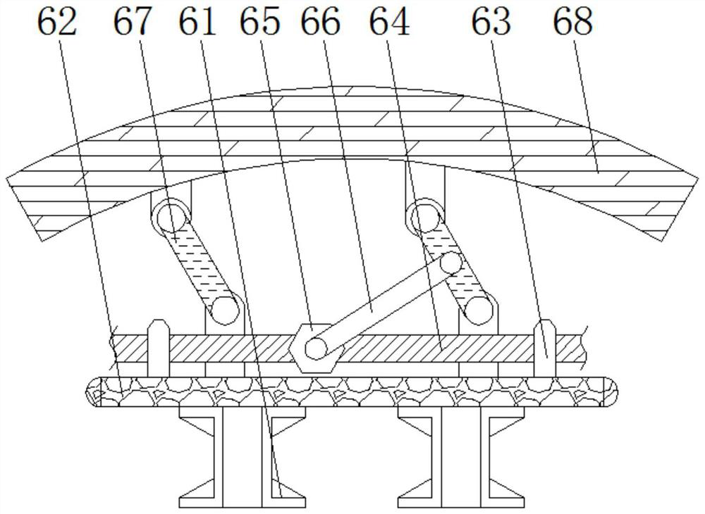
[0029] The locking mechanism 6 comprises a base 61, the top of the base 61 is welded with a device plate 62, the top of the device plate 62 is welded with a limit sleeve 63, the inside of the limit sleeve 63 is connected with a drive shaft 64 for rotation, and the lock mechanism 6 is provided with Five groups with the same internal structure and specifications, five groups of locking mechanisms 6 are evenly distributed around the center of the device...

Embodiment 3

[0033] see Figure 1-4 , a constant speed winding device for optical fiber manufacturing, comprising a drive disc 1, characterized in that: the outer side of the drive disc 1 is welded with a connecting plate 2, the outer side of the connecting plate 2 is welded with a locking disc 3, and the front of the drive disc 1 is rotationally connected There is a device plate 4, the centers of the drive plate 1, the lock plate 3 and the device plate 4 are on the same straight line, and there are five connecting plates 2, which are evenly distributed around the center of the drive plate 1 and welded to the drive plate 1 respectively. the periphery;

[0034] The diameter of the locking disc 3 is larger than that of the driving disc 1, and the shape of the locking disc 3 is a ring, and five connecting plates 2 are welded between the locking disc 3 and the driving disc 1; the device disc 4 is rotatably connected to the driving disc 1, and the diameter of the device disk 4 is smaller than ...


PUM


Abstract

The invention relates to the technical field of optical fiber manufacturing, and discloses a constant-speed winding device for optical fiber manufacturing. The device comprises a driving disc, connecting plates are welded to the outer side of the driving disc, a locking disc is welded to the outer sides of the connecting plates, a device disc is rotationally connected to the front face of the driving disc, trigger mechanisms are arranged on the front face of the driving disc, and locking mechanisms are arranged on the front face of the device disc; and circle centers of the driving disc, the locking disc and the device disc are located on the same straight line. According to the constant-speed winding device for optical fiber manufacturing, through matched use of the driving disc and the trigger mechanisms, when the winding speed of an optical fiber is too high, contact blocks can be in contact with contacts, so that the locking mechanisms are started; and through matched use of driving shafts and sliding blocks, when the driving shafts rotate, the sliding blocks move, under hinging of support rods, brake blocks are pushed to be in contact with the inner side of the locking disc, so that the speed reducing effect is achieved, constant-speed winding work is guaranteed, further, the optical fiber manufacturing efficiency is improved, and economic loss caused by optical fiber breakage is avoided.

Description

technical field [0001] The invention relates to the technical field of optical fiber manufacturing, in particular to a constant-speed winding device for optical fiber manufacturing. Background technique [0002] Optical fiber, short for optical fiber, is a fiber made of glass or plastic that acts as a means of light transmission. In daily life, optical fibers are used for long-distance information transmission because the loss of light in optical fibers is much lower than that of electricity in wires. In the manufacture of optical fibers, the raw materials are turned into filaments by high temperature. In order to facilitate the subsequent processing, it is usually necessary to wind the produced filaments. However, due to the particularity of the optical fiber material, it is difficult for the existing equipment to ensure a uniform winding speed during winding, which may cause the optical fiber to be wound. Breakage and breakage are caused during the process. At this time,...

Claims


Application Information

Patent Timeline
Patent Type & Authority Applications(China)
IPC IPC(8): B65H59/38B65H54/74B65H54/70
CPCB65H54/70B65H54/74B65H59/382B65H2701/32
Inventor 李硕仪
Owner 厦门时不待贸易有限公司
Why Eureka
Try Eureka