Device and method for moving equipment in wind power generation tower

A mobile device and tower technology, which is applied in the direction of lifting equipment braking device, wind turbine, installation/support configuration of wind turbine, etc. It can improve the efficiency of maintenance and replacement, save maintenance and replacement time, and reduce costs.

Pending Publication Date: 2021-08-31
上海电气研砼(木垒)建筑科技有限公司
View PDF7 Cites 0 Cited by
  • Summary
  • Abstract
  • Description
  • Claims
  • Application Information

AI Technical Summary

Problems solved by technology

[0004] (1) As the diameter of the tower becomes larger and the weight of the equipment increases, the span of the fixed hanging beam increases, and the strength requirements become higher and higher, resulting in an increase in the processing cost of the hanging beam;
[0005] (2) Since the concrete tower needs to be prefabricated with formwork, the reserved mounting holes for the hanging beams are fixed, resulting in a fixed position of the hanging beams, making it difficult to adapt to different electrical equipment requirements of different manufacturers;
[0006] (3) Each fan must be installed, resulting in an increase in the cost of the entire wind power project (processing and installation);
[0007] (4) Due to the uncertainty of the electrical equipment failure of each fan, the utilization rate of the fixed hanging beam is uncertain, resulting in waste of resources

Method used

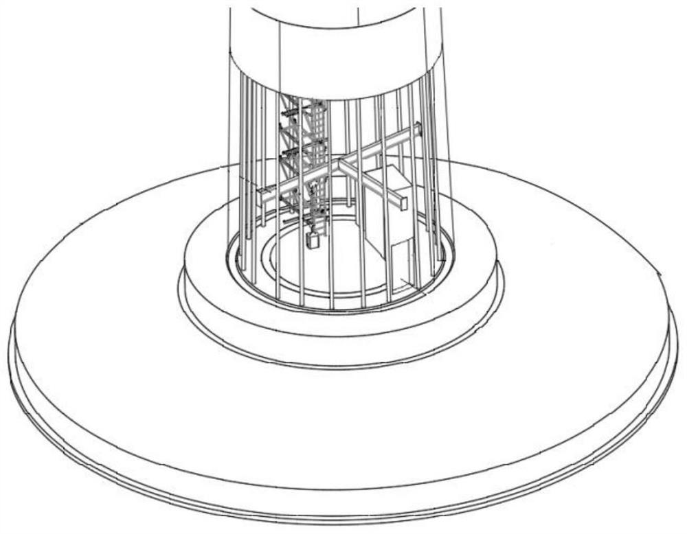
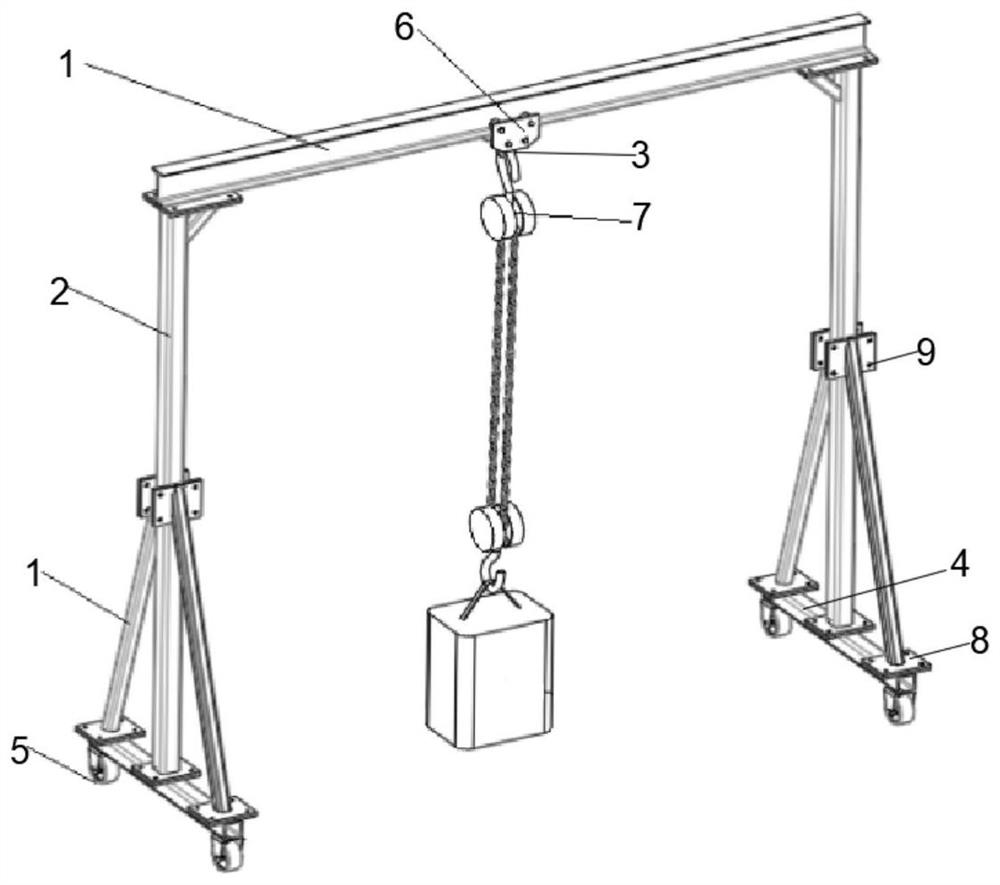
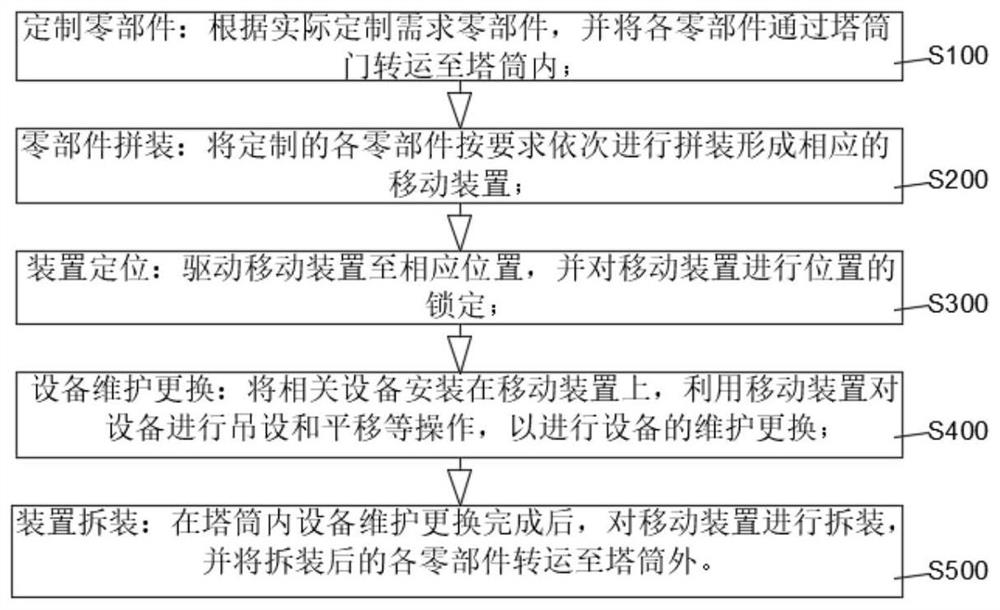

Image

  • Device and method for moving equipment in wind power generation tower
  • Device and method for moving equipment in wind power generation tower
  • Device and method for moving equipment in wind power generation tower

Examples


Embodiment Construction

[0027] The device and method for moving equipment in the wind power tower of the present invention will be described in more detail below in conjunction with schematic diagrams, wherein a preferred embodiment of the present invention is shown. It should be understood that those skilled in the art can modify the present invention described here, and still The advantageous effects of the present invention are realized. Therefore, the following description should be understood as the broad knowledge of those skilled in the art, but not as a limitation of the present invention.

[0028] In the following paragraphs the invention is described more specifically by way of example with reference to the accompanying drawings. Advantages and features of the present invention will be apparent from the following description and claims. It should be noted that all the drawings are in a very simplified form and use imprecise scales, and are only used to facilitate and clearly assist the pur...


PUM


Abstract

The invention discloses a device and method for moving equipment in a wind power generation tower. The device comprises a horizontal I-shaped steel hanging beam, wherein main supporting columns are detachably installed at two ends of the bottom surface of the horizontal I-shaped steel hanging beam through bolts, a hoisting mechanism is movably installed on the horizontal I-shaped steel hanging beam, bases are detachably installed on the bottom surfaces of the two main supporting columns through bolts, and universal wheels are installed at two ends of the bottom surfaces of the bases. The device is simple and reasonable in structural design, low in cost, capable of being customized according to actual conditions and high in flexibility. When equipment in the tower drum is maintained and replaced, it is not needed that one mobile device is arranged on each piece of equipment, so that the operation cost is greatly reduced; and meanwhile, the moving device is convenient to mount and dismount and flexible to operate, the maintenance and replacement time of equipment in the tower is effectively saved, and therefore the maintenance and replacement efficiency of the equipment in the tower is effectively improved.

Description

technical field [0001] The invention relates to the technical field of tower construction, in particular to a device and method for moving equipment inside a wind power tower. Background technique [0002] In recent years, wind turbines have shown a tendency to become larger. As the height of the tower continues to increase, the diameter of the bottom of the tower also increases. Especially the concrete prefabricated tower, because it is not restricted by transportation conditions, the diameter of the bottom is getting larger and larger. , in terms of space, it can basically meet the placement needs of the electrical control equipment required by the fan. With the increasing number of electrical equipment at the bottom of the tower, the corresponding maintenance, maintenance, and replacement of parts have also increased. Especially for dry-type transformers, the iron core is very heavy, and it is inconvenient to maintain and replace inside the tower. Lifting and translation...

Claims


Application Information

Patent Timeline
Patent Type & Authority Applications(China)
IPC IPC(8): B66C19/02B66C5/02B66C9/08B66C9/10F03D13/20F03D80/00
CPCB66C19/02B66C5/02B66C9/08B66C9/10F03D13/20F03D80/00Y02E10/728Y02E10/72
Inventor 张冬王艳冬于洁霞
Owner 上海电气研砼(木垒)建筑科技有限公司
Why Eureka
Try Eureka