
Laundry treatment apparatus

A clothing treatment device and drainage surface technology, which is applied to washing devices, other washing machines, household clothes dryers, etc., can solve problems such as unsatisfactory sanitation, stink, and inability to pass through washing water

Pending Publication Date: 2021-08-31
LG ELECTRONICS INC
View PDF8 Cites 0 Cited by
  • Summary
  • Abstract
  • Description
  • Claims
  • Application Information

AI Technical Summary

Problems solved by technology

[0006] However, with regard to the existing laundry treatment device that can wash the filter, although the problem of the decline in drying performance can be minimized from the aspect of the washable heat exchanger, the fluff separated from the heat exchanger by washing If foreign matter remains on the drain flow path where the condensed water is discharged, and the foreign matter remaining on the drain flow path is left for a long time, it will cause odor and is not ideal in terms of hygiene
[0007] In addition, in the conventional clothes treatment device, although the movement of foreign matter is guided by supplying more than an appropriate amount of washing water, so that the foreign matter such as fluff washed in the heat exchanger is discharged together with the condensed water of the washing heat exchanger, but according to the drainage The structural shape of the flow path and the direction of the flow path of the washing water will form a dead zone where the washing water cannot pass through, so that even if more than an appropriate amount of washing water is supplied, the foreign matter remaining in the dead zone cannot be mixed with the washing water. Exhausted problem points

Method used


Image

  • Laundry treatment apparatus
  • Laundry treatment apparatus
  • Laundry treatment apparatus

Examples


Embodiment Construction

[0048] The name of each component in the process described in the present invention, as defined in consideration of functions in the present invention are defined. Thus, the technical elements should not be construed as limiting the present invention. Further, the respective constituent elements are defined name may be referred to other names in the art.

[0049] Referring to the drawings the laundry treatment apparatus according to an embodiment of the present invention will be described in detail.

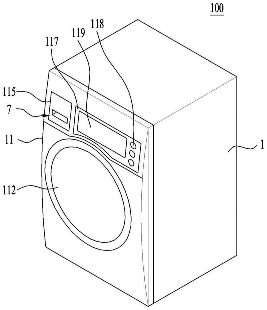
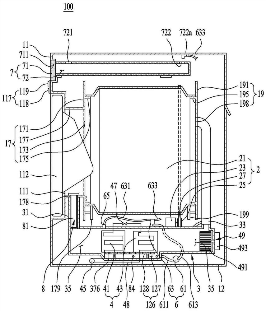
[0050] figure 1 Is a perspective view of the laundry treating apparatus according to the present invention, figure 2 It is a schematic view showing an internal structure of the laundry treating apparatus according to the present invention.

[0051] like Figure 1 to 2, The laundry treating apparatus 100 comprises: a housing; drum 2, is rotatably disposed inside the case to provide storage space laundry; duct 3, the drum 2 is formed from the air discharged again supplied to the drum 2...


PUM


Abstract

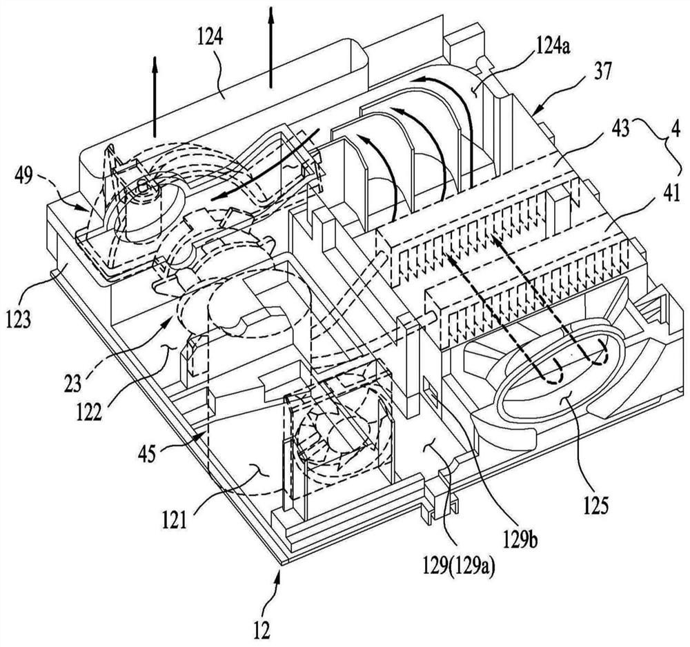
The present invention relates to a laundry treatment apparatus which includes a cabinet forming an external appearance of the apparatus and configured to have a base, a drum rotatably provided in the cabinet, a driver provided in the base to rotate the drum, a duct fastened to the base to form a circulation passage communicating with the drum, a heat pump having a heat exchanger provided in the circulation passage to cool air, and a discharge unit to discharge water generated by the heat exchanger. The base includes a water collection chamber configured to collect the water generated by the heat exchanger, and formed to have at least one discharge surface having different angles of inclination, thereby guiding flow of condensate water; and a discharge hole located adjacent to the water collection chamber, and formed to communicate with the water collection chamber in a manner that water guided by the at least one discharge surface is discharged through the discharge unit.

Description

Technical field [0001] The present invention relates to a laundry processing apparatus, and more particularly, to a laundry treating apparatus comprising an improved drain structure of the base laundry treatment apparatus. Background technique [0002] Laundry treating apparatus is a device for washing laundry, and means are collectively capable of drying washed laundry and the laundry drying laundry are achieved. [0003] A laundry treatment apparatus in a conventional laundry treating apparatus may be in the drying laundry comprising: a drum, providing storage space laundry; duct, a flow path of air discharged from the drum again supplied to the drum; a first heat exchanger, removed from the drum by cooling air flowing into the duct of moisture contained in the air; a second heat exchanger, the air passing through the first heat exchanger for heating; and a fan, having passed through the second heat exchanger to the air cylinder moves. [0004] In the conventional laundry treat...

Claims


Application Information

Patent Timeline
IPC IPC(8): D06F39/08D06F39/00D06F35/00D06F25/00
CPCD06F39/006D06F39/083D06F35/008D06F25/00D06F58/24D06F58/22D06F58/20D06F58/206D06F58/26D06F58/12D06F2103/36D06F2103/56D06F2105/28D06F2105/30
Inventor 金宗律南泫守金映秀
Owner LG ELECTRONICS INC
Learn More