Main cable internally-penetrating assembly type steel cross beam of vehicle cableway bridge

A technology of assembled and steel beams, which is applied in bridges, buildings, etc.

Pending Publication Date: 2021-08-31
GUILIN UNIVERSITY OF TECHNOLOGY +1
View PDF0 Cites 0 Cited by
  • Summary
  • Abstract
  • Description
  • Claims
  • Application Information

AI Technical Summary

Problems solved by technology

Obviously, the practice of using steel pins to connect the steel beam members of the existing cableway bridge does not meet the requirements of the above codes

Method used


Image

  • Main cable internally-penetrating assembly type steel cross beam of vehicle cableway bridge
  • Main cable internally-penetrating assembly type steel cross beam of vehicle cableway bridge
  • Main cable internally-penetrating assembly type steel cross beam of vehicle cableway bridge

Examples


Embodiment 1

[0044] This embodiment is applicable to the structure of the in-line steel beam. Taking a cableway bridge with a main span of 438m as a design example, the design load is -80 for cars and -80 for hanging.

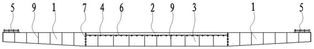
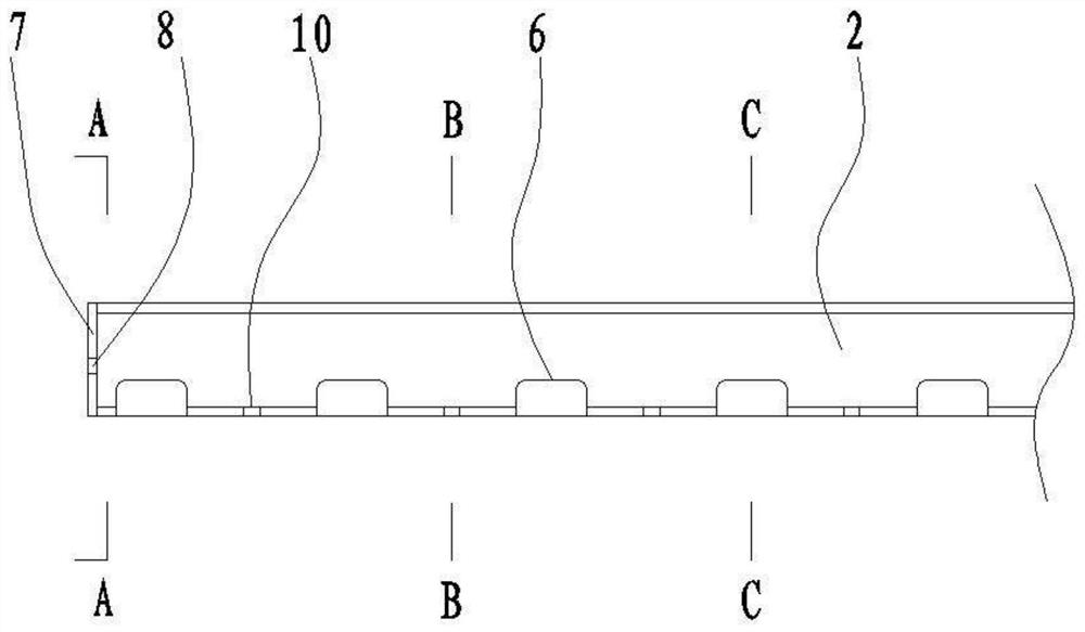
[0045] Such as Figure 1 to Figure 13As shown, this embodiment includes two beam side segments 1 and a middle section between the two beam side segments 1, and the lengths of the beam side segments 1-middle section-beam side segment 1 are sequentially For, 3520mm, 6000mm and 3520mm. The middle section includes the upper section 2 of the middle section of the beam and the lower section 3 of the middle section of the beam with the same length. The upper section 2 of the middle section of the beam and the lower section 3 of the middle section of the beam are stacked up and down. The lengths of the upper section 2 of the middle section and the lower section 3 of the middle section of the crossbeam are both 6000 mm, that is, the length ratio of the side section 1 of the crossb...

Embodiment 2

[0053] This embodiment is applicable to the structure of inverted figure-eight steel beams. Taking a cableway bridge with a main span of 438m as a design example, the design load is -80 for cars and -80 for hanging.

[0054] Specifically, on the basis of Embodiment 1, according to the design requirements, the upper flange plate of the beam side section 1 in this embodiment is further tilted upward, so that the end section of the beam forms a symmetrical inverted eight in the cross section of the bridge. glyph structure. At the same time, some adaptive adjustments are made to the structure of the web of the beam side segment 1 and the structure of the roller assembly 5 .

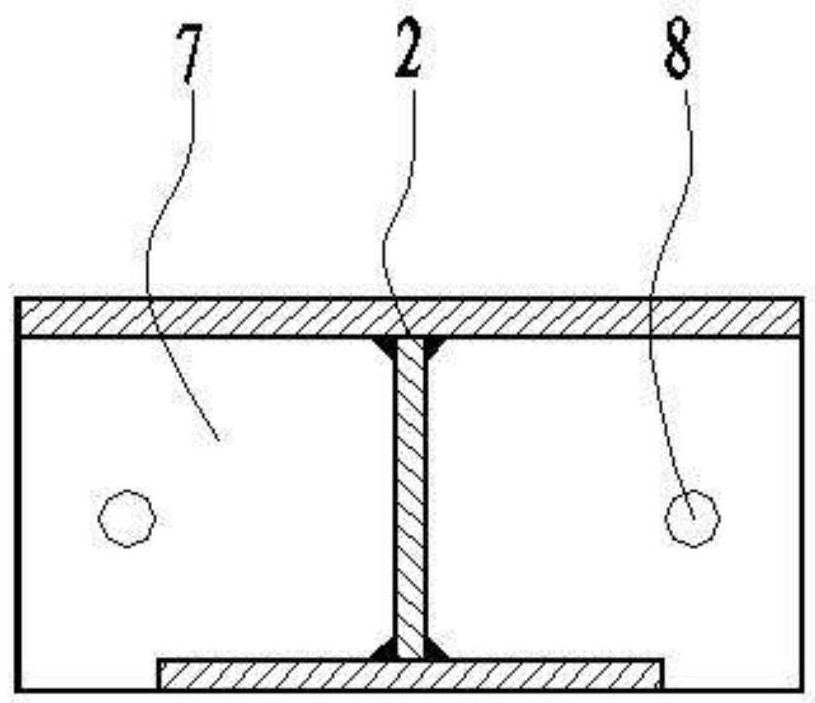
[0055] The beneficial effect of the present invention is that the bridge deck cables pass through the steel beam web, not only can omit the special bridge deck for the beam of the traditional cableway bridge, but also adopt the traditional beam installation method of the cableway bridge to install the steel ...


PUM


Abstract

The invention relates to the field of cableway bridge engineering construction, in particular to a main cable internally-penetrating assembly type steel cross beam of a vehicle cableway bridge, which comprises two cross beam side sections, a cross beam middle section upper section and a cross beam middle section lower section. The cross beam middle section upper section and the cross beam middle section lower section are the same in length, and the cross beam middle section upper section is fixed on the upper surface of the cross beam middle section lower section through high-strength bolts. The two cross beam side section sections are symmetrically arranged at the two ends of the cross beam middle section lower section, and the two ends of the cross beam middle section lower section and the two ends of the cross beam middle section upper section are fixedly connected with the ends of the two cross beam side section sections through high-strength bolts respectively. Roller assemblies are arranged at the ends, away from each other, of the two cross beam side segment sections in a welded mode, and a plurality of cable holes are evenly formed in the bottom of the cross beam middle section upper section in the length direction. According to the invention, an assembled structure is adopted, the structure is simple, factory-like welding prefabrication and on-site high-strength bolt connection assembly can be realized, installation can still be carried out by using a current common suspension unfolding erection method, and the construction is convenient.

Description

technical field [0001] The invention relates to the field of engineering construction of cableway bridges, in particular to an assembled steel crossbeam of a main cable penetrating inside of a vehicle cableway bridge. Background technique [0002] According to "Modern Cableway Bridge" (Huang Shaojin, Liu Bosheng, People's Communications Publishing House, 2004): In the deck structure of a cableway bridge, the steel beam is an important link between the deck cable and the stabilizing cable. It can not only strengthen the bridge It also plays a role in distributing the load on the bridge deck. The beam can be made into an inverted figure-eight shape, or a straight shape, and its cross section can be a combined box-shaped cross-section formed by welding steel plates and channel steels, or an H-shaped steel cross-section. For the convenience of transportation, the steel beam is often divided into three sections with a middle part and two end parts. When the beams are erected, t...

Claims


Application Information

Patent Timeline
Patent Type & Authority Applications(China)
IPC IPC(8): E01D2/00E01D2/02
CPCE01D2/00E01D2/02
Inventor 景天虎陈雪辉余文成蒋志军谢建新蒋承峰蒋文娉叶飚蒋旭秦健张小飞陈华张济民蒋雪蕾肖世华黄俊
Owner GUILIN UNIVERSITY OF TECHNOLOGY
Why Eureka
Try Eureka