
Tuned mass damper with self-energy-dissipation vibrator

A technology for tuning mass damping and vibrators, applied in building components, building types, shockproof, etc., can solve problems such as engineering application reliability affecting product service life, large weight and structural size of electromagnetic damping devices, etc., to increase the effective mass ratio , reduce the total weight, increase the effect of vibration absorption

Inactive Publication Date: 2021-08-31
王剑
View PDF0 Cites 0 Cited by
  • Summary
  • Abstract
  • Description
  • Claims
  • Application Information

AI Technical Summary

Problems solved by technology

The energy consumption mechanism of electromagnetic damping refers to the way of using the device to convert the mechanical energy of the vibrator into electrical energy and then into heat energy. Electromagnetic damping has no direct contact loss of objects, and the product has a long service life and does not require maintenance. It is a relatively cutting-edge technology at present. The energy dissipation device of the damper has a certain impact on the vibration reduction effect, but it mainly affects the service life of the product and the reliability of engineering applications
However, although electromagnetic damping has a long service life and high reliability, the weight and structural size of the electromagnetic damping device are generally large

Method used


Image

  • Tuned mass damper with self-energy-dissipation vibrator
  • Tuned mass damper with self-energy-dissipation vibrator
  • Tuned mass damper with self-energy-dissipation vibrator

Examples


Embodiment Construction

[0026] The present invention will be described in further detail below in conjunction with the accompanying drawings and specific embodiments.

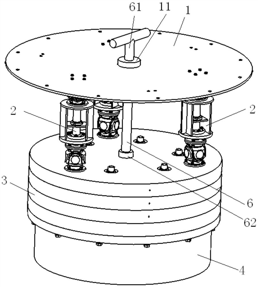
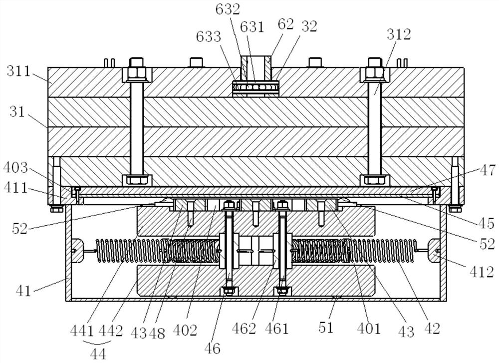
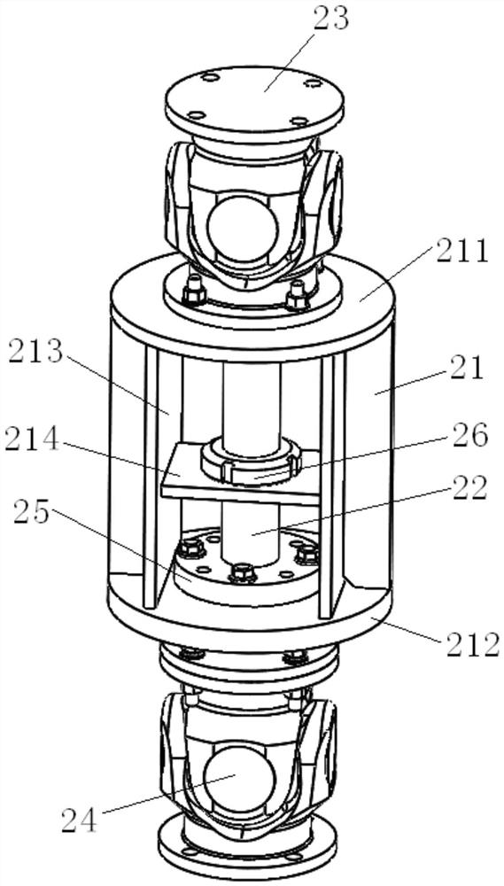
[0027] like figure 1 and figure 2 As shown, the tuned mass damper with self-consumption vibrator in this embodiment includes a load bearing plate 1, a swing rod assembly 2 and a self-consumption vibrator. The self-consumption vibrator includes a primary vibrator 3 and an energy dissipation device 4. The vibrator 3 includes a primary mass 31, the upper end of the swing rod assembly 2 is hinged to the bearing plate 1, and the lower end is hinged to the primary mass 31. The energy dissipation device 4 includes a housing 41, a tension spring 42, a magnetic steel 43, and a secondary vibrator 44 and a conductor plate 45, the top of the housing 41 is provided with a connection part 411, the connection part 411 is connected to the primary mass block 31, the conductor plate 45 is installed on the connection part 411, the tension spring 42, t...


PUM


Abstract

The invention discloses a tuned mass damper with a self-energy-dissipation vibrator. The tuned mass damper comprises a bearing plate, a swing rod assembly and the self-energy-dissipation vibrator, the self-energy-dissipation vibrator comprises a first-stage vibrator and an energy dissipation device, the first-stage vibrator comprises a first-stage mass block, the two ends of the swing rod assembly are hinged to the bearing plate and the first-stage mass block respectively, the energy dissipation device comprises a shell, multiple tension springs, magnetic steel, a second-stage vibrator and a conductor plate, the shell is connected with the first-stage mass block through a connecting part, the conductor plate is installed on the connecting part, the second-stage vibrator comprises an upper-layer mass block and a lower-layer mass block, an installation gap is formed between the upper-layer mass block and the lower-layer mass block, the lower-layer mass block is movably arranged on the bottom wall of the shell, the tension springs are horizontally arranged in the installation gap, the two ends of the tension springs are connected with the inner wall of the shell and a fastening assembly respectively, the magnetic steel is arranged at the top of the upper-layer mass block, and a gap is formed between the magnetic steel and the conductor plate. According to the tuned mass damper with the self-energy-dissipation vibrator, the energy dissipation part of the damper is replaced by a complete small damper, the effective mass ratio of the vibrator is increased, the vibration absorption effect is improved, and the total weight is reduced.

Description

technical field [0001] The invention relates to a vibration control device, in particular to a tuned mass damper with a self-consumption vibrator. Background technique [0002] Tuned mass dampers (TMDs) and tuned liquid dampers (TLDs) are widely used in bridges, high-rise buildings and wind power engineering for vibration control. The working principle of the damper is to absorb the energy of the controlled equipment through resonance, and then dissipate the energy through the energy dissipation device, thereby reducing the vibration of the controlled equipment. [0003] The damper is generally composed of a vibrator, an energy dissipation device, a limit device, and a support and fixing device. The vibration absorption effect of the damper is mainly determined by the effective mass of the vibrator, the greater the effective mass, the better the effect. The ratio of the effective vibrator mass to the total mass of the damper is called the effective mass ratio. The larger t...

Claims


Application Information

Patent Timeline
IPC IPC(8): E04H12/22E04B1/98
CPCE04B1/98E04H12/22E04H12/2253E04H12/2292
Inventor 王健
Owner 王剑
Learn More