An adaptive multi-inertia channel hydraulic mount and its adaptive method

A hydraulic mount and inertial channel technology, applied in the direction of spring/shock absorber, shock absorber, shock absorber-spring combination, etc., can solve the problems of low lag angle peak frequency, complex hydraulic mount structure, and high cost , to achieve the effect of increasing the damping coefficient, improving the vibration isolation effect and saving costs

Active Publication Date: 2020-04-14
HEFEI UNIV OF TECH
View PDF7 Cites 0 Cited by
  • Summary
  • Abstract
  • Description
  • Claims
  • Application Information

AI Technical Summary

Problems solved by technology

[0005] Aiming at the deficiencies of the prior art, the present invention provides an adaptive multi-inertia channel hydraulic mount and its adaptive method. The hydraulic mount has the advantages of simple structure, low cost and high efficiency, and solves the problem of hydraulic mount structure Complex, costly, low lag angle peak frequency problem

Method used


Image

  • An adaptive multi-inertia channel hydraulic mount and its adaptive method
  • An adaptive multi-inertia channel hydraulic mount and its adaptive method
  • An adaptive multi-inertia channel hydraulic mount and its adaptive method

Examples


Embodiment 1

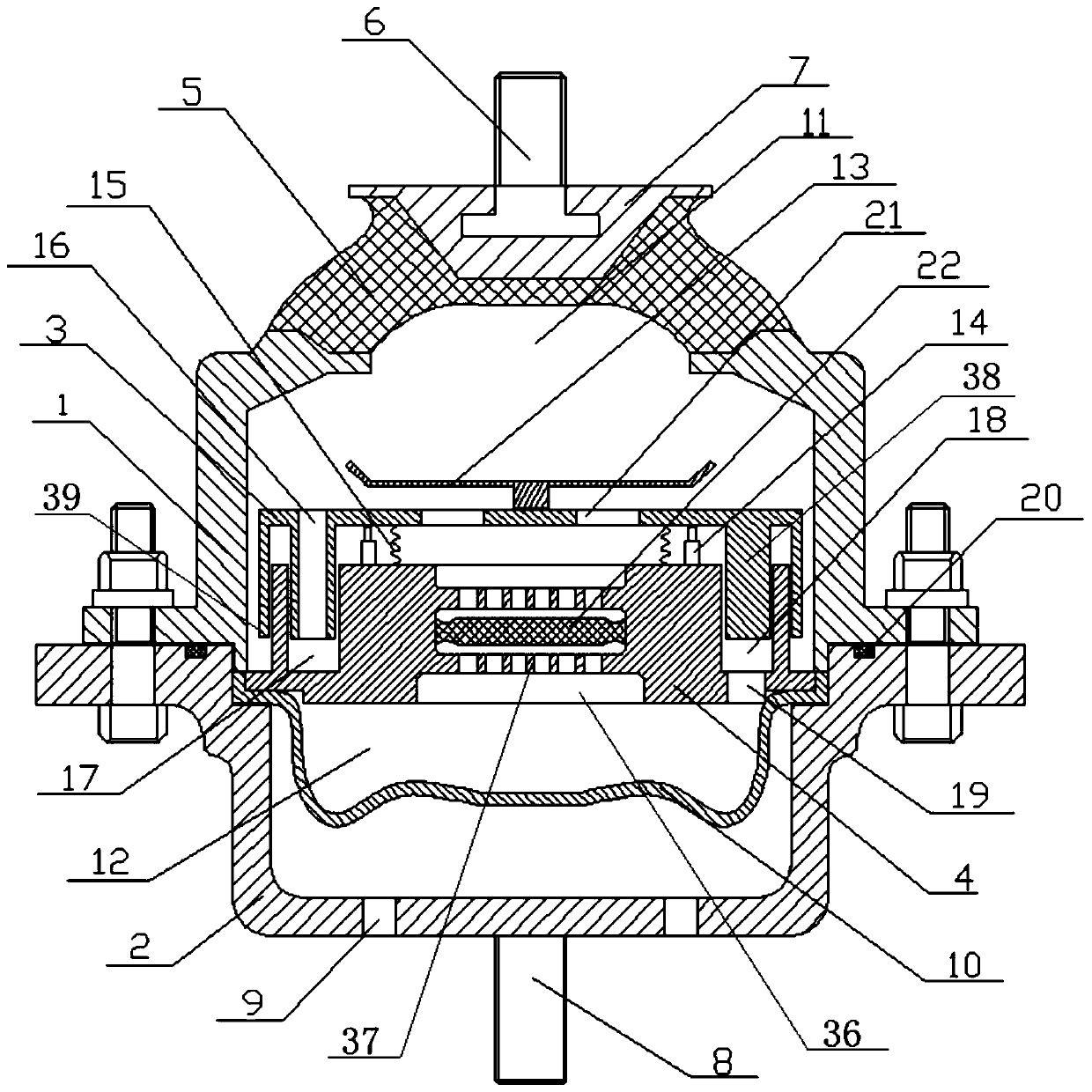
[0048] see Figure 1-3 , The adaptive multi-inertia channel hydraulic mount in this embodiment includes an upper cover assembly, a lower cover assembly, a vibration isolation mechanism, a leather cup 10 and a sealing ring 20 .

[0049] The upper cover assembly includes upper cover 1, rubber main spring 5, upper bolt 6, and reinforcing block 7. Wherein, the top end of upper bolt 6 is installed on the engine, and the reinforcing block 7 is installed at the bottom of upper bolt 6 . Rubber main spring 5 is installed on the bottom of reinforcing block 7, and loam cake 1 is installed on the bottom of rubber main spring 5. Among them, the rubber main spring 5, the upper bolt 6, and the reinforcing block 7 can be fixed by a vulcanization process. Through the above process, the installation among the rubber main spring 5, the upper bolt 6 and the reinforcing block 7 can be made more stable, thereby ensuring the long-term use of the hydraulic mount and improving the safety of the hydr...

Embodiment 2

[0063] see Figure 9 , this embodiment is similar to Embodiment 1 and the only difference is that the up and down movement of the mobile frame 3 in this embodiment is controlled by the first drive unit 13a and the second drive unit 13b, and the booster plate 13 and the guide structure are removed. 14 and spring 15. The bottom ends of the first driving unit 13 a and the second driving unit 13 b are installed on the partition 4 , and their other ends are installed on the side of the moving frame 3 facing the partition 4 . The first driving unit 13a and the second driving unit 13b can be driven by a motor or a hydraulic cylinder. In idling conditions, starting conditions, rapid acceleration conditions, or impact conditions such as passing through uneven roads, the first drive unit 13a and the second drive unit 13b control the size and implementation of the inertial channel cross-sectional area that the moving frame 3 moves to. Same as Example 1. Under high-frequency vibration,...

Embodiment 3

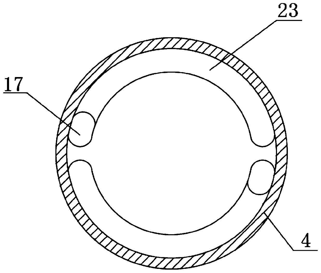
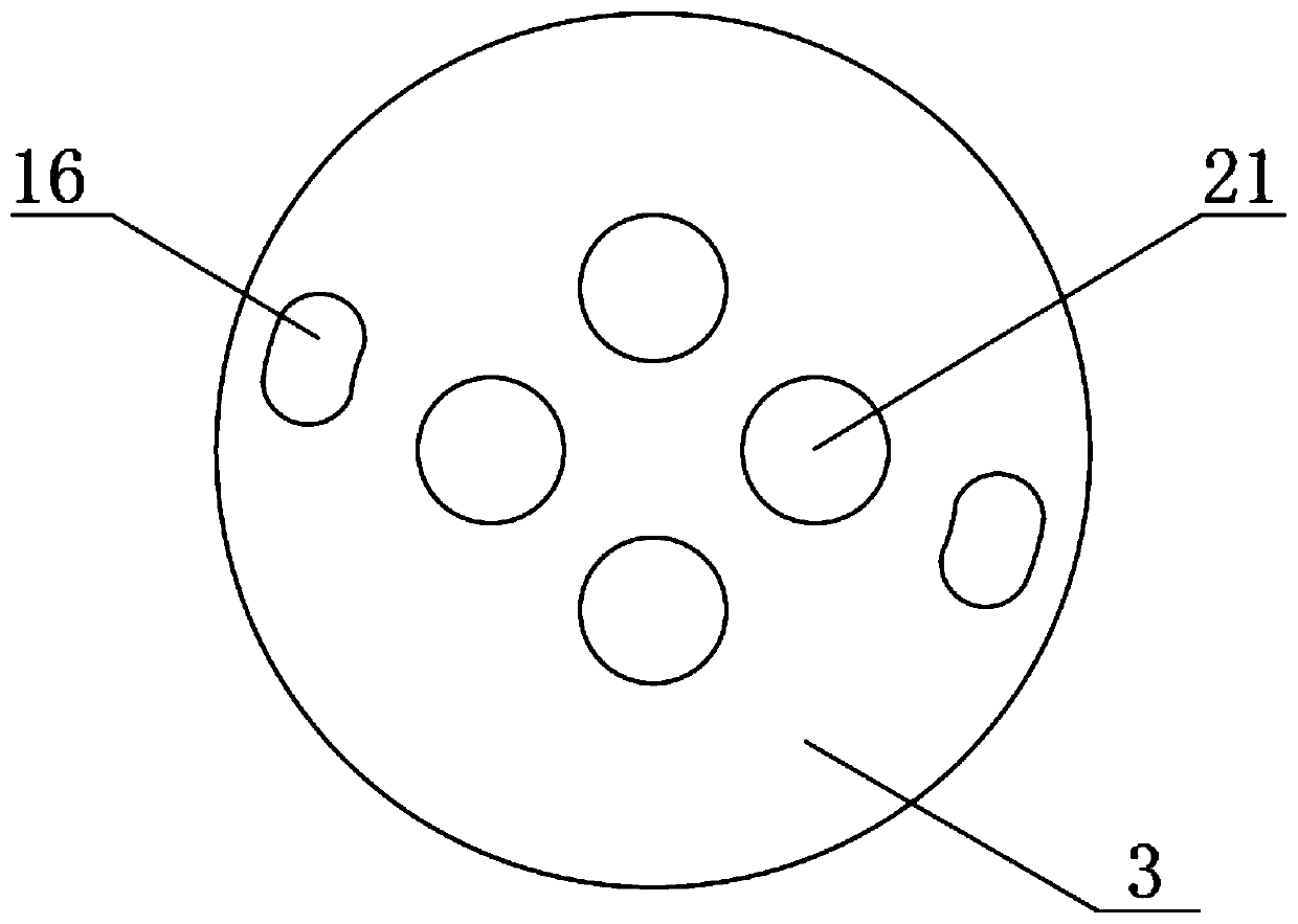
[0065] see Figure 10 with Figure 11 In this embodiment, three arc-shaped runners 23 corresponding to a central angle of 110 degrees are used, and the lengths of the three runners are not limited to the same length, and different lengths can also be used. The three flow channels 23, the three pipes 16, the three first blind holes 17, and the three second blind holes 18 correspond one by one to form three inertial passages. These three inertial passages can make the liquid circulation of the hydraulic device more rapid and the structure more stable. At the same time, the total cross-sectional area of ​​the inertial passages is increased, thereby further increasing the damping coefficient of the liquid and further improving the vibration absorption capacity of the hydraulic mount. , thereby increasing the vibration-absorbing effect.

[0066]In summary, the present invention adjusts the cross-sectional area of ​​the inertial channel by moving the moving frame 3 up and down, so...


PUM


Abstract

The invention discloses a self-adaptive multi-inertia-channel type hydraulic mount and a self-adaption method thereof. A vibration isolation mechanism is arranged in a cavity of the hydraulic mount and comprises an isolation plate, a moving frame and a telescopic structure. The cavity is divided by the isolation plate into an upper liquid chamber and a lower liquid chamber. At least one first blind hole is formed in the side, facing the upper liquid chamber, of the isolation plate, and at least one second blind hole corresponding to the at least one first blind hole is formed in the side, facing the lower liquid chamber, of the isolation plate. At least one mounting groove communicating with the upper liquid chamber and the lower liquid chamber is formed in the isolation plate. A runner communicating with the first blind holes and the corresponding second blind holes is formed in the isolation plate. A decoupling film is fixed in each mounting groove, and the decoupling films disconnect the way that the mounting grooves communicate with the upper liquid chamber and the lower liquid chamber. According to the hydraulic mount, through up-and-down movement of the moving frame, the cross sectional area of inertia channels is adjusted, the aim of adjusting output damping force and rigidity is achieved, the hydraulic mount can meet different requirements under different work conditions, and meanwhile the vibration isolation effect is improved.

Description

technical field [0001] The invention relates to a hydraulic mount in the technical field of mounts, in particular to an adaptive multi-inertia channel hydraulic mount and an adaptive method thereof. Background technique [0002] Automotive engine hydraulic mount refers to the elastic connection system between the engine powertrain and the vehicle frame. The design of the system's damping performance is directly related to the transmission of engine vibration to the vehicle body. The ordinary rubber suspension developed first is widely used because of its low price and simple structure. However, the dynamic characteristics of the rubber suspension components have two shortcomings: first, the vibration damping is too small, which cannot meet the requirements of the vibration isolation and damping performance of the vehicle powertrain suspension system in the low frequency domain; Dynamic hardening will occur during vibration, resulting in a significant increase in dynamic sti...

Claims


Application Information

Patent Timeline
Patent Type & Authority Patents(China)
IPC IPC(8): F16F13/10
CPCF16F13/105F16F13/107
Inventor 胡金芳朱冬东高东阳
Owner HEFEI UNIV OF TECH
Why Eureka
Try Eureka