A pdc drill bit capable of casing drilling and its design method

A casing drilling and design method technology, applied in the direction of drill bits, drilling equipment, earthwork drilling and production, etc., can solve the problems of low drilling plug efficiency, casing damage, increasing the gap between the gauge and the well wall, etc., to achieve Avoid cutting casing effects

Active Publication Date: 2021-10-08
CCDC PETROLEUM CORING TECH
View PDF16 Cites 0 Cited by
  • Summary
  • Abstract
  • Description
  • Claims
  • Application Information

AI Technical Summary

Problems solved by technology

However, the traditional drilling cement plugs and casing accessories all use roller cone bits. The efficiency of drilling the plugs is low. Security Risk
[0003] When using a conventional PDC drill bit to cut cement in the casing, the drill bit will not cut the casing under ideal conditions (such as figure 1 shown), but due to the complex situation at the bottom of the well, the drill bit will also oscillate around the central axis in addition to its rotation during the drilling process (such as figure 2 shown), so that the drill bit produces a longitudinal force Fx close to the well wall. Under the action of Fx and the circumferential cutting force Fy, the oscillating cutting of the drill bit close to the gauge at the cutting teeth will increase the gap between the gauge and the well wall clearance, and the cutting teeth cut into the bushing, causing damage to the bushing

Method used


Image

  • A pdc drill bit capable of casing drilling and its design method
  • A pdc drill bit capable of casing drilling and its design method
  • A pdc drill bit capable of casing drilling and its design method

Examples


Embodiment 1

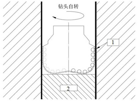
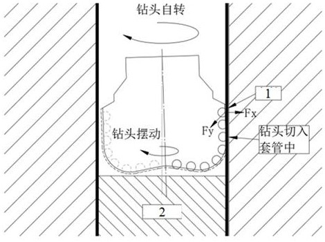
[0044]In order to solve the problems existing in the traditional PDC drill bit when drilling into the cement section 2 in the casing, a design method for a PDC drill bit capable of casing drilling is specifically provided in this embodiment. The technical principle of the design method is: adopt 6 points The isolation method isolates the PDC drill bit from the casing 1 to prevent the cutting teeth 6 on the drill bit from cutting the casing during drilling. Take the 6-point isolation method as an example, such as Figure 5 As shown, the design method includes:

[0045] Install and arrange 6 isolation units 5 on the blade gauge part 4 of the PDC drill bit, and each isolation unit 5 is made of hard alloy. surface 8, and it can ensure that the continuation of drilling efficiency after drilling out of the casing 1 is not affected), but in actual application, it is not limited to only arranging six isolation units 5. It should be noted that: if the number of isolation units 5 If t...

Embodiment 2

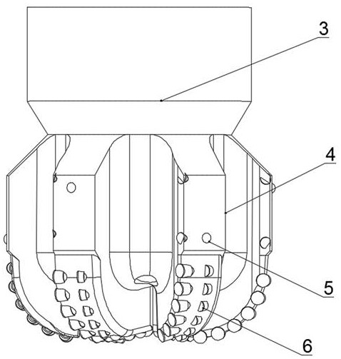
[0057] In Embodiment 1, a design method of a PDC drill bit capable of casing drilling is provided, and a corresponding PDC drill bit is designed according to the design method provided. Drilling PDC bits such as image 3 , Figure 4 As shown, it includes a drill body 3, a plurality of blades evenly distributed on the drill body 3 along the same circumferential direction, and each blade is divided into a gage part and a cutting tooth part 6, and the PDC drill bit also includes:

[0058] Two isolation unit groups, each isolation unit group is provided with 3 isolation units 5 (there are 6 isolation units 5 in total in the two isolation unit groups), each isolation unit 5 is made of hard alloy, and the same isolation unit Each isolation unit 5 of the group is respectively arranged on the gage part of each described blade and is surrounded by each isolation unit 5 of this isolation unit group to form a virtual plane 7; In the present embodiment, each isolation unit group respecti...


PUM


Abstract

The invention discloses a casing drillable PDC drill bit and a design method thereof, which belong to the technical field of petroleum drilling. At least 6 isolation units are arranged on the blade gauge part of the PDC drill bit; The units are divided into at least two groups, and each isolation unit of each group is respectively arranged on each blade gauge part along the same circumferential direction, and a virtual plane is respectively surrounded by each isolation unit of each group; After the intersection lines between the pipe and well walls are connected, a virtual contact surface can be formed. When the PDC bit is drilling, the virtual contact surface is in contact with the casing wall, so as to have drill plugs and drill casing accessories without damaging the casing. , The purpose of continuing to drill fully after exiting the casing.

Description

technical field [0001] The invention belongs to the technical field of oil drilling, and in particular relates to a PDC drill bit capable of casing drilling and a design method thereof. Background technique [0002] In order to meet the engineering requirements, it is often necessary to run the casing in the drilled section first, and pour cement into it to cement the well, and then drill the cement layer (or called: cement plug) when it is necessary to continue drilling. Achieve deeper drilling. However, the traditional drilling cement plugs and casing accessories all use roller cone bits. The efficiency of drilling the plugs is low. Security Risk. [0003] When using a conventional PDC drill bit to cut cement in the casing, the drill bit will not cut the casing under ideal conditions (such as figure 1 shown), but due to the complex situation at the bottom of the well, the drill bit will also oscillate around the central axis in addition to its rotation during the drilli...

Claims


Application Information

Patent Timeline
Patent Type & Authority Patents(China)
IPC IPC(8): E21B10/54E21B10/43
CPCE21B10/43E21B10/54
Inventor 姚建林李勇陈晗董仕明冯明周刚刘彬周兴郑凯中黄伟干建华张伟付晓平
Owner CCDC PETROLEUM CORING TECH
Why Eureka
Try Eureka