A Quasi-Zero Stiffness Vibration Isolator Using Destabilizable Simply Supported Beams as Positive Stiffness Loading Elements
A quasi-zero stiffness, load-bearing element technology, applied in the functional characteristics of spring/shock absorber, design characteristics of spring/shock absorber, spring/shock absorber, etc., can solve the problems of small vibration isolation interval and large vibration isolation frequency , to achieve the effect of large vibration isolation range, low dynamic stiffness, and excellent bearing performance
- Summary
- Abstract
- Description
- Claims
- Application Information
AI Technical Summary
Problems solved by technology
Method used
Image
Examples
specific Embodiment approach 1
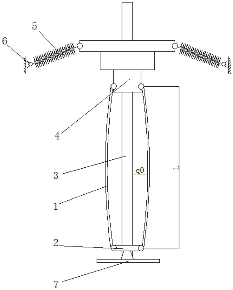
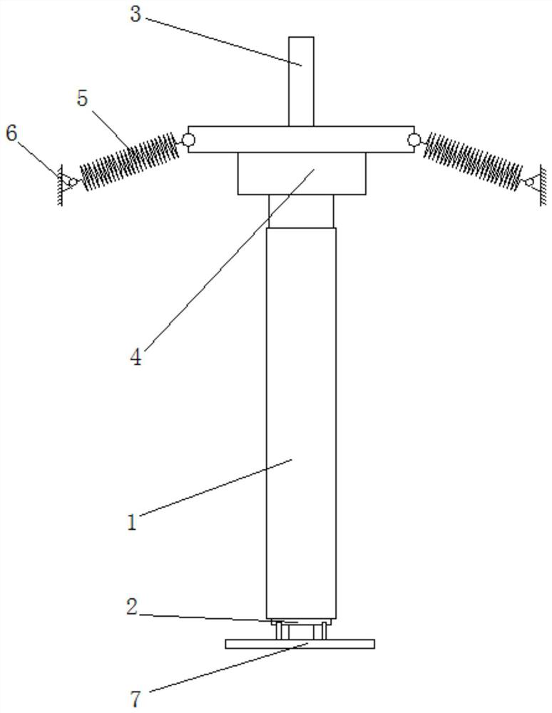
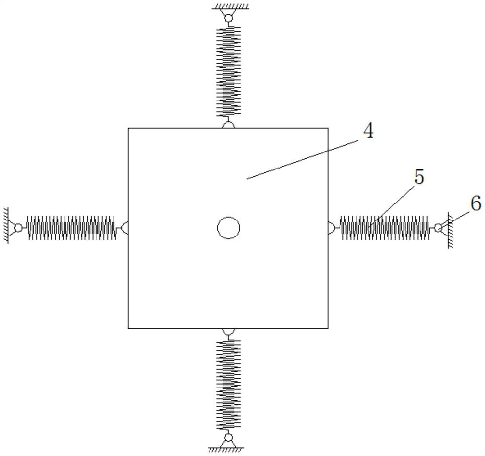
[0024] Specific implementation mode one: refer to Figure 1 to Figure 4 Describe this embodiment. This embodiment provides a quasi-zero-stiffness vibration isolator with a destabilizable simply supported beam as a positive-stiffness bearing element. The quasi-zero-stiffness vibration isolator includes two simply supported beams 1 and a lower hinged seat 2 , guide rod 3, bearing platform 4, multiple vibration isolation units and base 7;
[0025] The guide rod 3 is vertically arranged on the base 7, and one end of the guide rod 3 is affixed to the upper surface of the base 7, the lower hinge seat 2 is sleeved on the bottom of the guide rod 3, and the lower hinge seat 2 is fixed on the On the upper surface of the base 7, the bearing platform 4 is sleeved on the top of the guide rod 3, and the bearing platform 4 is slidingly connected with the guide rod 3, and two simply supported beams 1 are relatively arranged on both sides of the bearing platform 4, and each simple One end of ...
specific Embodiment approach 2
[0027] Specific implementation mode two: refer to Figure 1 to Figure 4 This embodiment is described. This embodiment is to further limit the simply supported beam 1 described in the first specific embodiment. In this embodiment, the simply supported beam 1 is an arc-shaped plate structure. Other compositions and connection methods are the same as those in Embodiment 1.
[0028] With this arrangement, the initial state of the simply supported beam 1 is an arc-shaped structure, which is beneficial for the simply supported beam 1 to be bent along the arc direction after the platform bears heavy objects, and the deformation direction of the simply supported beam 1 when the force is applied is clearly defined.
specific Embodiment approach 3
[0029] Specific implementation mode three: refer to Figure 1 to Figure 4 Describe this embodiment, this embodiment is to further limit the lower hinged seat 2 described in the second specific embodiment, in this embodiment, the lower hinged seat 2 includes a fixed plate and two support seats, the top surface of the fixed plate A through hole is processed in the center, and two support seats are arranged under the fixed plate, and the two support seats are arranged opposite to each other along the axis of the through hole. Each support seat is fixedly connected with the lower surface of the fixed plate, and the fixed plate passes through the through hole sleeve Located at the lower part of the guide rod 3, two hinge points are arranged on the fixed plate, and each hinge point is set correspondingly to a simply supported beam 1. Other compositions and connection methods are the same as those in the second embodiment.
[0030] In this way, the lower hinge seat 2 is used to prov...
PUM
 Abstract
Description
Claims
Application Information
 - R&D
- Intellectual Property
- Life Sciences
- Materials
- Tech Scout
- Unparalleled Data Quality
- Higher Quality Content
- 60% Fewer Hallucinations
Browse by: Latest US Patents, China's latest patents, Technical Efficacy Thesaurus, Application Domain, Technology Topic, Popular Technical Reports.
© 2025 PatSnap. All rights reserved.Legal|Privacy policy|Modern Slavery Act Transparency Statement|Sitemap|About US| Contact US: help@patsnap.com


