
Lithium battery leakage detection equipment

A leak detection, lithium battery technology, applied in the direction of detecting the appearance of fluid at the leak point, using liquid/vacuum degree for liquid tightness measurement, etc., can solve the leakage of easily missed detection battery products, low detection efficiency, and slow detection efficiency and other problems, to achieve the effect of improving detection efficiency, high degree of automation, and simple action

Pending Publication Date: 2021-08-31
东莞市群立自动化科技有限公司
View PDF0 Cites 4 Cited by
  • Summary
  • Abstract
  • Description
  • Claims
  • Application Information

AI Technical Summary

Problems solved by technology

The traditional lithium battery leak detection usually uses manual to judge whether the battery is damaged from the appearance of the product, not only the detection efficiency is slow, but also the detection rate is high; another common detection method is CCD camera detection. In the edge banding, CCD camera is used for detection, it is easy to miss the phenomenon, and the missed detection rate is relatively high
[0003] In the existing battery leakage detection method, the battery is generally placed in the test cavity in multiple layers, and the elevator pulls the multi-layer tray to realize the layered pick-and-place of the battery. The structure is complex and the detection efficiency is low; at the same time, the top of the test cavity and The bottom is arranged with a vacuum interface, a positive pressure charging structure, and a test gas circuit interface. In this way, the airflow is evenly distributed in the length direction of the battery to be tested, and it is easy to miss the leakage of battery products with large differences in aspect ratio.

Method used


Image

  • Lithium battery leakage detection equipment
  • Lithium battery leakage detection equipment
  • Lithium battery leakage detection equipment

Examples


Embodiment Construction

[0056] The technical solutions in the embodiments of the present invention will be clearly and completely described below in conjunction with the drawings in the present invention. Apparently, the described embodiments are only some of the embodiments of the present invention, not all of them. Based on the embodiments of the present invention, all other embodiments obtained by persons of ordinary skill in the art without making creative efforts belong to the protection scope of the present invention.

[0057] It should be noted that the terms "first" and "second" in the description and claims of the present application and the above drawings are used to distinguish similar objects, but not necessarily used to describe a specific sequence or sequence. It should be understood that the data so used may be interchanged under appropriate circumstances for the embodiments of the application described herein. Furthermore, the terms "comprising" and "having", as well as any variations...


PUM


Abstract

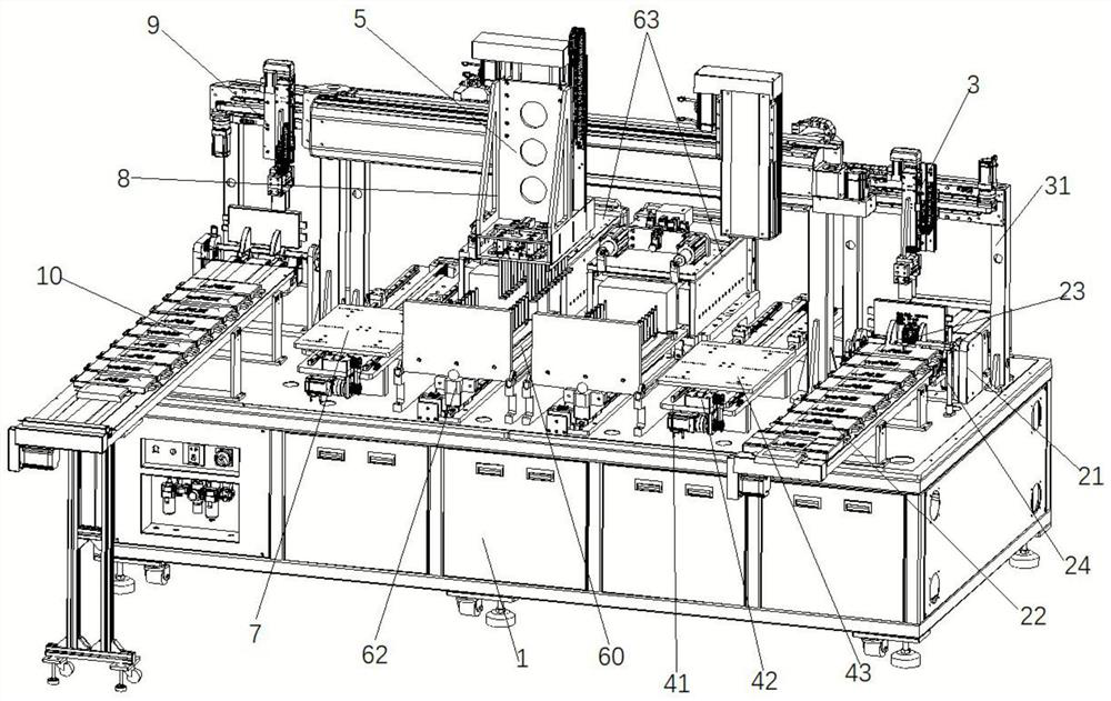
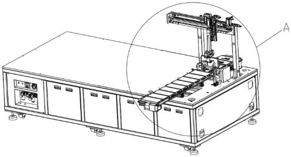
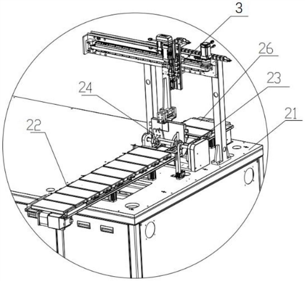
The invention belongs to the technical field of battery detection, and particularly relates to lithium battery leakage detection equipment. The lithium battery leakage detection equipment comprises a cabinet, and an overturning feeding device, a feeding carrying device, a feeding transfer carrying platform, a test carrying device and a battery test device which are installed on the cabinet. The feeding transfer carrying platform is located between the overturning feeding device and the battery testing device. The feeding carrying device is located above the tail end of the overturning feeding device and matched with the overturning feeding device so that the batteries can be vertically carried to the feeding transfer carrying platform. The test carrying device is positioned above the feeding transfer carrying platform and the battery test device and is matched with the feeding transfer carrying platform and the battery test device, so that the battery is vertically carried into the battery test device. Compared with the prior art, the lithium battery leakage detection equipment has the advantages that full-automatic control of the leakage detection equipment is realized, the automation degree is high, the detection efficiency of the equipment can be greatly improved, and the labor intensity of workers and the omission ratio are reduced.

Description

technical field [0001] The invention belongs to the technical field of battery detection, in particular to a lithium battery leakage detection device. Background technique [0002] With the popularity of new energy vehicles, the output of automotive power batteries is increasing year by year, and the demand for batteries in society is gradually increasing. The traditional lithium battery leak detection usually uses manual to judge whether the battery is damaged from the appearance of the product, not only the detection efficiency is slow, but also the detection rate is high; another common detection method is CCD camera detection. In the edge banding, CCD camera is used for detection, and it is easy to miss the phenomenon, and the missed detection rate is relatively high. [0003] In the existing battery leakage detection method, the battery is generally placed in the test cavity in multiple layers, and the elevator pulls the multi-layer tray to realize the layered pick-and...

Claims


Application Information

Patent Timeline
Patent Type & Authority Applications(China)
IPC IPC(8): G01M3/04
CPCG01M3/04
Inventor 尹峰谢健敏陈强王佳佳
Owner 东莞市群立自动化科技有限公司
Learn More