
Receiving and transmitting antenna electrical axis alignment debugging method

A technology of transmitting antenna and receiving antenna, applied in the field of debugging of the electrical axis alignment of receiving and transmitting antennas, can solve the problems of high labor intensity, time-consuming, cumbersome and other problems, and achieve the effect of solving the problem of high labor intensity and low debugging efficiency.

Active Publication Date: 2021-08-31
THE RES INST FOR SPECIAL STRUCTURES OF AERONAUTICAL COMPOSITE AVIC
View PDF7 Cites 0 Cited by
  • Summary
  • Abstract
  • Description
  • Claims
  • Application Information

AI Technical Summary

Problems solved by technology

[0016] The above-mentioned debugging methods are relatively cumbersome, labor-intensive, time-consuming, and low-precision.

Method used


Image

  • Receiving and transmitting antenna electrical axis alignment debugging method
  • Receiving and transmitting antenna electrical axis alignment debugging method
  • Receiving and transmitting antenna electrical axis alignment debugging method

Examples


Embodiment Construction

[0063] In order to make the purpose, technical solutions and advantages of the embodiments of the present invention more clear, the technical solutions in the embodiments of the present invention will be clearly and completely described below in conjunction with the drawings in the embodiments of the present invention. Apparently, the described embodiments are some, but not all, embodiments of the present invention. Based on the embodiments of the present invention, all other embodiments obtained by persons of ordinary skill in the art without making creative efforts belong to the protection scope of the present invention.

[0064] Features and exemplary embodiments of various aspects of the invention are described in detail below. In the following detailed description, numerous specific details are set forth in order to provide a thorough understanding of the present invention. It will be apparent, however, to one skilled in the art that the present invention may be practice...


PUM


Abstract

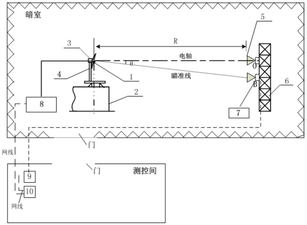
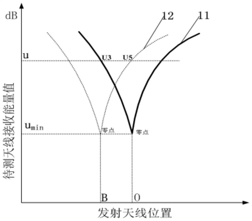
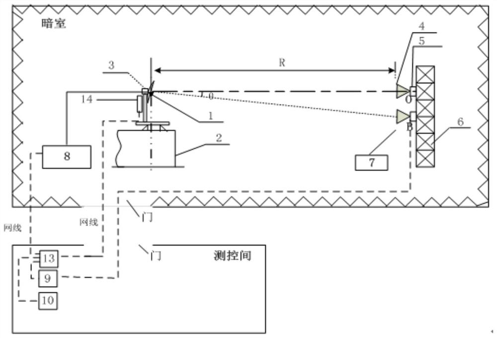
The invention provides a receiving and transmitting antenna electrical axis alignment debugging method. The method comprises the following steps of during debugging, controlling an industrial control all-in-one machine 14, controlling a servo controller 9 and checking a vector network analyzer 8 in real time without leaving a turntable body 2; enabling a transmitting antenna 5 to move through the industrial control all-in-one machine 14, checking a V-shaped difference directional diagram measured by a vector network analyzer 8 in real time, and stopping moving the transmitting antenna 5 when the transmitting antenna 5 is moved to a position B and the V-shaped difference directional diagram has a zero point position; according to the deviation direction of the transmitting antenna, reversely debugging the small-angle positioner 3, and when u is equal to u3, indicating that the zero point moves to a position O; and checking a V-shaped difference directional diagram measured by the vector network analyzer 8 so that the zero point appears at the O position of the transmitting rack, moving the transmitting antenna 5 to the O position of the transmitting rack, and completing electrical axis alignment of the receiving antenna and the transmitting antenna. The debugging method is very simple, a large amount of debugging time is saved, the testing efficiency is improved, and the debugging precision is ensured.

Description

technical field [0001] The invention relates to the technical field of electromagnetic characteristic test of aviation radome, in particular to a debugging method for aligning electric axes of receiving and transmitting antennas. Background technique [0002] The debugging of the electrical axis alignment of the receiving and transmitting antennas of the aviation radome plays a key role in the quality of signal reception and transmission, however, its accuracy is not satisfactory. The applicant has been devoting himself to the debugging and improvement of the electrical axis alignment of the receiving and transmitting antennas of the aviation radome. [0003] For example, when the applicant is currently studying the aiming error test of the radome of the PL-12 seeker, it is necessary to adjust the electrical axis alignment of the receiving and transmitting antennas. Due to the small size of the PL-12 seeker radome, it is very difficult to make the antenna seat to electrical...

Claims


Application Information

Patent Timeline
Patent Type & Authority Applications(China)
IPC IPC(8): G01R1/02G01R29/10H01Q3/02H01Q1/12
CPCG01R1/02G01R29/10H01Q3/02H01Q1/12Y02P90/02
Inventor 李传兰孟平
Owner THE RES INST FOR SPECIAL STRUCTURES OF AERONAUTICAL COMPOSITE AVIC
Learn More