Optical imaging lens

An optical imaging lens and lens technology, applied in optics, optical components, instruments, etc., can solve problems such as poor imaging quality

Active Publication Date: 2021-08-31
ZHEJIANG SUNNY OPTICAL CO LTD
View PDF7 Cites 0 Cited by
  • Summary
  • Abstract
  • Description
  • Claims
  • Application Information

AI Technical Summary

Problems solved by technology

[0004] The main purpose of the present invention is to provide an optical imaging len...

Method used


Image

  • Optical imaging lens
  • Optical imaging lens
  • Optical imaging lens

Examples


Embodiment 1

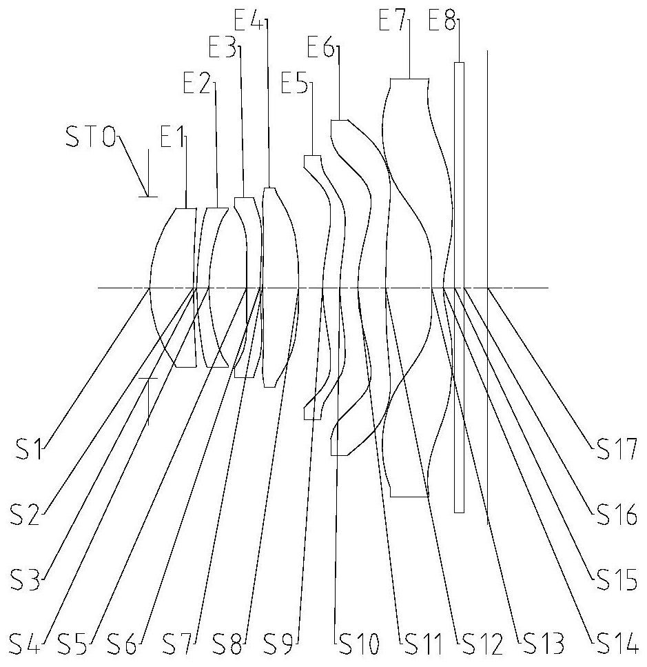
[0067] Such as Figure 1 to Figure 48 As shown, the optical imaging lens sequentially includes an iris diaphragm, a first lens, a second lens, a third lens, a fourth lens, a fifth lens, a sixth lens and a seventh lens along the optical axis from the object side to the image side; The object side of the fifth lens is convex; wherein, the central thickness CT1 of the first lens on the optical axis, and the air space T67 of the sixth lens and the seventh lens on the optical axis satisfy: CT1 / T67<1.0; optical imaging The distance T1 between the iris diaphragm of the largest entrance pupil of the lens and the image side of the first lens on the optical axis and the aperture value FNO1 corresponding to the maximum entrance pupil of the optical imaging lens satisfy: 0.5

[0068] By setting the object side of the fifth lens into a convex surface, the processability of the surface shape of the fifth lens and the structural strength of the fifth lens are ensured. By limiti...

Embodiment 2

[0083] Such as Figure 1 to Figure 48 As shown, the optical imaging lens includes sequentially from the object side to the image side along the optical axis: an iris stop; a first lens; a second lens; a third lens; a fourth lens; a fifth lens, and the object side of the fifth lens is Convex surface; the sixth lens; the seventh lens; wherein, the central thickness CT1 of the first lens on the optical axis, the air interval T67 of the sixth lens and the seventh lens on the optical axis satisfy: CT1 / T67<1.0; optical The maximum entrance pupil diameter EPD1 of the imaging lens and half the Semi-FOV of the maximum field of view of the optical imaging lens satisfy: EPD1*tan(Semi-FOV)<3.0mm.

[0084] By setting the object side of the fifth lens into a convex surface, the processability of the surface shape of the fifth lens and the structural strength of the fifth lens are ensured. By limiting the ratio between the central thickness CT1 of the first lens on the optical axis and the ...


PUM


Abstract

The invention provides an optical imaging lens. The optical imaging lens sequentially comprises from an object side to an image side along an optical axis, a variable diaphragm; a first lens; a second lens; a third lens; a fourth lens; a fifth lens, wherein the object side surface of the fifth lens is a convex surface; a sixth lens; a seventh lens; wherein the central thickness CT1 of the first lens on the optical axis and the air interval T67 of the sixth lens and the seventh lens on the optical axis meet the condition that CT1/T67 is less than 1.0; the distance T1 from the variable diaphragm of the maximum entrance pupil of the optical imaging lens to the image side surface of the first lens on the optical axis and the aperture value FNO1 corresponding to the maximum entrance pupil of the optical imaging lens meet the following condition of 0.5<T1/FNO1<1.0. A problem that in the prior art, an optical imaging lens is poor in imaging quality is solved.

Description

technical field [0001] The present invention relates to the technical field of optical imaging equipment, in particular to an optical imaging lens. Background technique [0002] In recent years, with the gradual popularization of smart terminals, people have higher and higher requirements for taking pictures with mobile phones. The rear cameras of major mainstream flagship phones are usually composed of an ultra-clear main camera, a super wide-angle lens, and a telephoto lens, which can be switched in different modes to achieve ultra-clear shooting. On the one hand, the combination of multiple cameras and algorithms can achieve higher-definition photography. On the other hand, the increase in the number of camera modules takes up more volume of the terminal, which is not conducive to the trend of miniaturization and thinning of mobile phones. [0003] That is to say, the optical imaging lens in the prior art has the problem of poor imaging quality. Contents of the inventi...

Claims


Application Information

Patent Timeline
IPC IPC(8): G02B13/00G02B13/18
CPCG02B13/0045G02B13/18G02B9/64
Inventor 陈念肖海东巫祥曦徐武超戴付建赵烈烽
Owner ZHEJIANG SUNNY OPTICAL CO LTD
Why Eureka
Try Eureka