
Inrush current control circuit for pluggable modules, pluggable modules

A technology of inrush current and control circuit, applied in the field of communication, can solve problems such as inability to effectively control inrush current, and achieve the effect of avoiding influence and suppressing inrush current.

Active Publication Date: 2021-11-19
SONT TECH (SHEN ZHEN) LTD +1
View PDF0 Cites 0 Cited by
  • Summary
  • Abstract
  • Description
  • Claims
  • Application Information

AI Technical Summary

Problems solved by technology

[0004] With the rapid increase of communication rate and port density, the usage of double-density golden finger type optical modules is increasing, such as double-density four-channel small form-factor pluggable package (Quad Small Form-factor Pluggable-DoubleDensity, QSFP-DD), dual Small Form-factor Pluggable-Double Density (SFP-DD), etc., because the gold finger connector is divided into two columns of additional gold fingers (Additional pads) and traditional gold fingers (Legacy pads), each column is There are several power contacts, and there is a gap between the two rows of contacts, so this type of optical module will go through the process of power on, power off, and power on when it is inserted into the device, and it will go through the process of power off, power on, and power off when the device is pulled out , because there are two consecutive power-on processes in a short period of time, the above-mentioned common inrush current control methods cannot effectively control the inrush current on such modules

Method used


Image

  • Inrush current control circuit for pluggable modules, pluggable modules
  • Inrush current control circuit for pluggable modules, pluggable modules
  • Inrush current control circuit for pluggable modules, pluggable modules

Examples


Embodiment 1

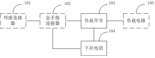
[0036] figure 1 It is a schematic structural diagram of the inrush current control circuit of the pluggable module in one embodiment of the present application, as shown in figure 1 As shown, a surge current control circuit of a pluggable module, the pluggable module is connected to the socket connector 101 of the inserted electronic device through the gold finger connector 102, and the gold finger connector 102 includes traditional gold finger connectors arranged side by side. Fingers (Legacy pads) and additional pads (Additional pads), the additional pads are located on the edge of the gold finger connector, the traditional gold fingers are located on the inner side of the gold finger connector, the traditional gold fingers and the additional pads contain useful One or more traditional power contacts and one or more increased power contacts for transmitting power signals, the circuit includes:

[0037] The load switch 103 is used to control the on and off of the load switch...

Embodiment 2

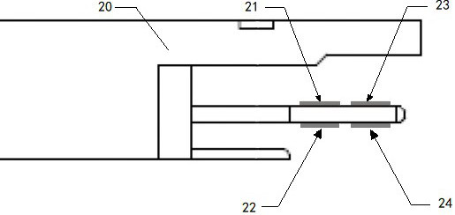
[0053] Figure 3a It is a schematic diagram of the top view function of the QSFP-DD optical module golden finger in another embodiment of the present application, Figure 3b It is a schematic diagram of the QSFP-DD optical module gold finger looking up function in another embodiment of the present application; as Figure 3a and Figure 3b As shown, the Additional QSFP-DD gold finger is an increased double-density four-channel small form-factor pluggable optical module gold finger, which is located on the edge of the circuit board plugging end; the Legacy QSFP28 gold finger is a traditional four-channel small form-factor pluggable optical module gold finger, Located on the inside of the plug-in end of the module, the VccTx, VccRx, Vcc1, VccTx1, VccRx1, and Vcc2 contacts are used to supply power to each functional unit in the module respectively, or they can be connected together to supply power to each functional unit in the module at the same time. The module manufacturer can...

Embodiment 3

[0057] Figure 5a It is a functional schematic diagram of the SFP-DD optical module golden finger in another embodiment of the present application, Figure 5b It is a schematic diagram of the SFP-DD optical module golden finger looking up function in another embodiment of the present application. As shown in the figure, the Additional SFP-DD golden finger is the added double-density small form-factor pluggable optical module golden finger, which is located on the edge of the plug-in end; the Legacy SFP golden finger is the traditional golden finger of the small form-factor pluggable optical module, which is located on the end inside. Among them, VccT, VccR, VccT1, and VccR1 are simultaneously used to supply power to each functional unit in the module.

[0058] The following describes the surge control circuit of the SFP-DD optical module in this embodiment.

[0059] like Figure 5b As shown, the VccT contact of the Legacy SFP gold finger of the SFP-DD optical module is con...


PUM


Abstract

The application relates to a surge current control circuit of a pluggable module and a pluggable module. The pluggable module is connected to the female connector of the inserted electronic device through the gold finger connector. The gold finger connector includes the traditional gold finger and the added gold finger arranged side by side. The added gold finger is located on the edge of the gold finger connector. The traditional The gold finger is located on the inner side of the gold finger connector. The traditional gold finger and the added gold finger respectively contain one or more traditional power contacts and one or more increased power contacts for transmitting power signals. The circuit includes a load Switch and pull-down resistor, the input terminal of the load switch is connected to one or more additional power contacts, one or more traditional power contacts; the enable terminal of the load switch is connected to any traditional power contact; the pull-down resistor is connected to the load The enable end of the switch is connected. The application circuit can effectively suppress the generation of surge current when the module is inserted into and pulled out of the device, so as to avoid the influence on the power supply network of the device.

Description

technical field [0001] The application belongs to the technical field of communication, and in particular relates to a surge current control circuit of a pluggable module and a pluggable optical module. Background technique [0002] As a fully functional electronic product, a pluggable module is composed of various components such as integrated circuit chips, transistors, resistors, capacitors, and inductors. Due to the use of decoupling capacitors, the entire circuit usually presents a capacitive load to the equipment power supply. Features, when the module is inserted into the device and the device is powered on, a large inrush current will easily be generated due to the charging of the decoupling capacitor. If it is not effectively controlled, it may cause a large drop in the power network voltage of the device, causing abnormal operation or even damage. [0003] The more common surge current control methods for pluggable optical modules are as follows: connect a PMOS tra...

Claims


Application Information

Patent Timeline
Patent Type & Authority Patents(China)
IPC IPC(8): H02H9/02G02B6/42
CPCG02B6/4287H02H9/02
Inventor 秦伟东郑波过开甲魏志坚孙鼎张伟
Owner SONT TECH (SHEN ZHEN) LTD
Learn More