
Scroll compressor

A technology of scroll compressors and scroll disks, applied in the direction of rotary piston machines, rotary piston pumps, mechanical equipment, etc., can solve the problem of increasing, difficult to increase the axial height of compression chamber C, and reducing durability question

Active Publication Date: 2021-08-31
HANON SYST
View PDF6 Cites 0 Cited by
  • Summary
  • Abstract
  • Description
  • Claims
  • Application Information

AI Technical Summary

Problems solved by technology

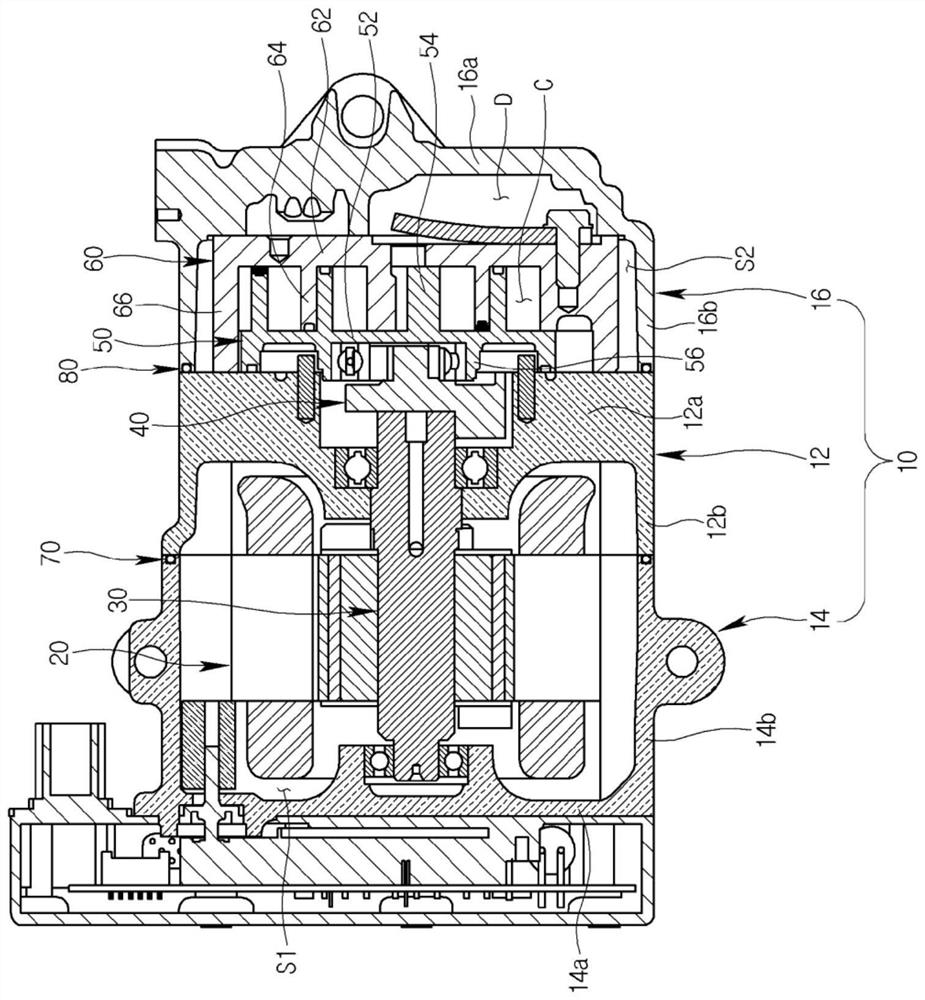
In addition, increasing the distance between the orbiting scroll hard plate 52 and the fixed scroll hard plate 62 and increasing the height of the orbiting scroll teeth 54 and the fixed scroll teeth 64 In this case, the durability of the orbiting scroll 50 and the fixed scroll 60 is significantly reduced, so it is also difficult to increase the axial height of the compression chamber C.

Method used


Image

  • Scroll compressor
  • Scroll compressor
  • Scroll compressor

Examples


Embodiment Construction

[0051] Hereinafter, the scroll compressor according to the present invention will be described in detail with reference to the drawings.

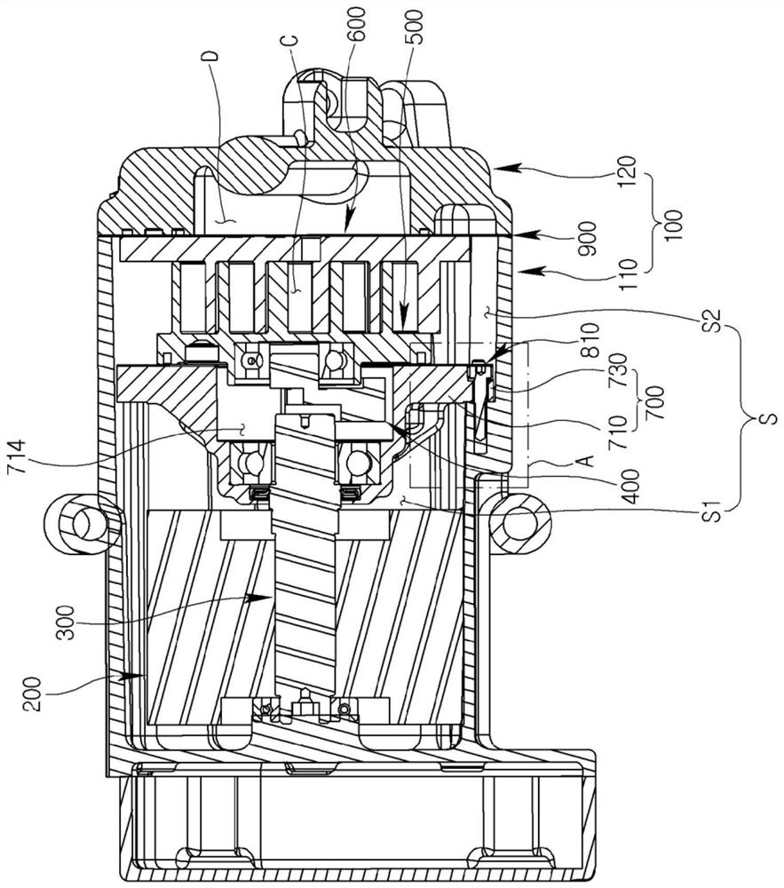
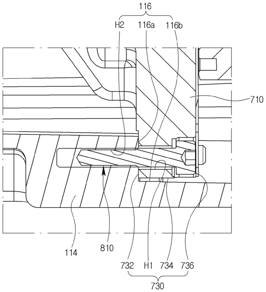
[0052] figure 2 is a sectional view showing a scroll compressor according to an embodiment of the present invention, image 3 yes figure 2 A magnified view of part A of the Figure 4 will be figure 2 The cross-sectional view of the scroll compressor cut from the other direction, Figure 5 yes Figure 4 A magnified view of part B of the Figure 6 From figure 2 A schematic diagram showing the first casing in a scroll compressor, Figure 7 From figure 2 A schematic diagram showing the main frame of a scroll compressor, Figure 8 is showing Figure 7 The schematic diagram of the back side, Figure 9 From figure 2 A schematic diagram showing a fixed scroll in a scroll compressor, Figure 10 is showing Figure 9 Schematic diagram of the back.

[0053] Refer to attached Figures 2 to 10 , The scroll compressor according to an...


PUM


Abstract

The present invention relates to a scroll compressor comprising: a casing; an orbiting scroll orbiting inside the casing; a fixed scroll engaging with the orbiting scroll so as to form two compression chambers in a pair; and a main frame for supporting the orbiting scroll, wherein the fixed scroll includes a fixed scroll end plate, and a fixed scroll wrap protruding from the fixed scroll end plate, and the main frame includes a main frame end plate provided at the opposite side of the fixed scroll end plate with respect to the orbiting scroll, and the fixed scroll end plate, the main frame end plate and the casing can form an orbiting space of the orbiting scroll. Therefore, the orbiting radius of the orbiting scroll is increased inside the casing having a predetermined size, so that a refrigerant discharge amount can be increased in a state in which the orbiting scroll and the fixed scroll are accommodated inside the casing.

Description

technical field [0001] The present invention relates to a scroll compressor, and more particularly, to a scroll compressor capable of compressing refrigerant using a fixed scroll and an orbiting scroll. Background technique [0002] Generally, an automobile is equipped with an air conditioning device (Air Conditioning, A / C) for cooling and heating a room. Such an air conditioner, as a structure of a refrigeration system, includes a compressor that compresses a low-temperature and low-pressure gas-phase refrigerant introduced from an evaporator into a high-temperature and high-pressure gas-phase refrigerant and sends it to a condenser. [0003] There are two types of compressors: a reciprocating type that compresses refrigerant according to the reciprocating motion of a piston, and a rotary type that performs compression while rotating. According to the transmission method of the drive source, the reciprocating type includes a crank type that uses a crank and multiple piston...

Claims


Application Information

Patent Timeline
Patent Type & Authority Applications(China)
IPC IPC(8): F04C18/02F04C29/00F04C27/00
CPCF04C18/0215F04C2240/805F04C2240/30F01C21/10F04C29/00F04C2210/26F04C2240/80F05B2210/14F05B2240/57F05B2260/30F04C2/025F04C15/0003F04C2240/40F04C18/02F04C18/0207F04C18/0246F04C18/0253
Inventor 李卿在徐祯基
Owner HANON SYST
Learn More