Recycling container and cleaning equipment

A container and storage cavity technology, which is applied to cleaning equipment, cleaning machinery, suction filters, etc., can solve the problems of difficult cleaning of recycling containers, and achieve stable and good filtering effect, easy cleaning, and convenient cleaning.

Pending Publication Date: 2021-09-03
PUPPY ELECTRONICS APPLIANCES INTERNET TECH (BEIJING) CO LTD
View PDF0 Cites 2 Cited by
  • Summary
  • Abstract
  • Description
  • Claims
  • Application Information

AI Technical Summary

Problems solved by technology

[0003] In view of the above analysis, the embodiment of the present invention aims to provide a recycling container and cleaning equipment to solve the problem of difficult cleaning of existing recycling containers

Method used


Image

  • Recycling container and cleaning equipment
  • Recycling container and cleaning equipment
  • Recycling container and cleaning equipment

Examples


Embodiment 1

[0067] This embodiment provides a recovery container, such as Figure 1 to Figure 15 ,include:

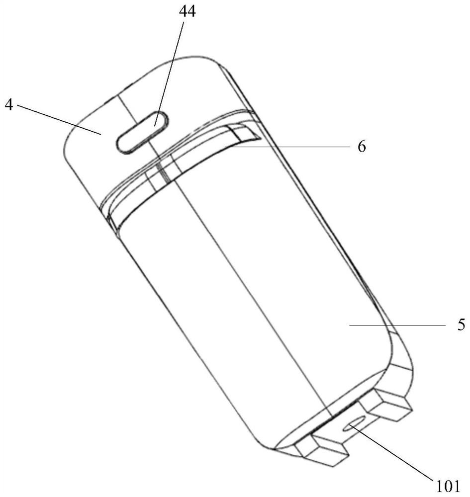
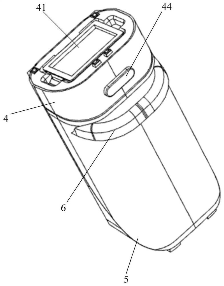
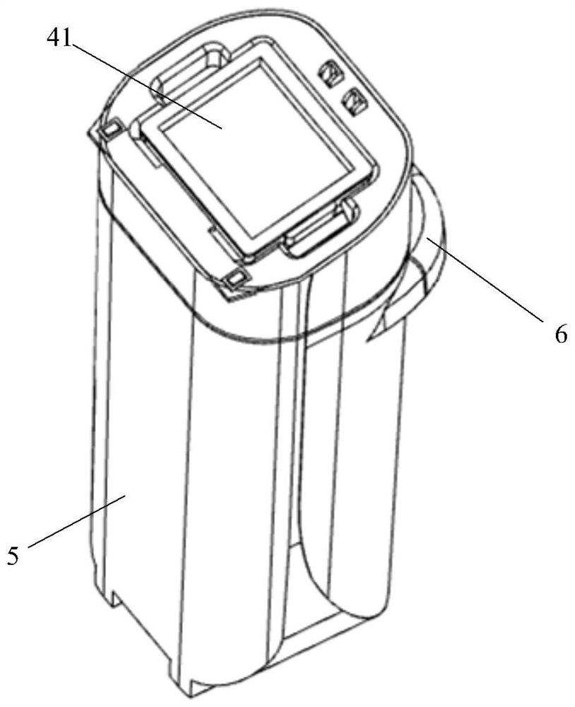
[0068] The recovery chamber 1 is provided with a fluid inlet 101, in case the dusty fluid enters the recovery chamber 1;

[0069] A filter barrel 2 is used for solid-liquid separation of the dusty fluid entering the recovery cavity 1; the filter barrel 2 is installed in the recovery cavity 1, and the filter barrel 2 is provided with a liquid inlet 201;

[0070] One end of the fluid pipe 3 communicates with the fluid inlet 101 , and the other end communicates with the liquid inlet 201 , so as to introduce the dust-laden fluid into the filter barrel 2 .

[0071] It should be noted that the above-mentioned dusty fluid includes solid debris (such as hair, debris, etc.), waste liquid and dusty airflow, etc., and the cleaning components of the cleaning equipment (such as floor brushes, roller brushes, etc.) are absorbed from the ground into the recovery container All substances are con...

Embodiment 2

[0124] This embodiment provides a cleaning device, including the recycling container provided in Embodiment 1.

[0125] Compared with the prior art, the cleaning equipment provided in this embodiment has the beneficial effect of the recovery container provided in Embodiment 1, and details will not be repeated here.

[0126] The recovery container is detachably installed in the cleaning equipment. Specifically, the cleaning equipment is provided with an assembly cavity suitable for the recovery container, and the recovery container is detachably installed in the assembly cavity through the pressing member 44 .

[0127] The above-mentioned cleaning equipment also includes a cleaning component, which communicates with the fluid inlet 101 of the recovery container, so as to prepare to introduce the dusty fluid absorbed by the cleaning component from the ground to be cleaned into the recovery container.

[0128] The above-mentioned cleaning components include roller brushes, floor ...


PUM


Abstract

The invention relates to a recycling container and cleaning equipment, belongs to the technical field of household appliances, and aims at solving the problem that an existing recycling container is difficult to clean. The recycling container comprises a recycling containing cavity provided with a fluid inlet for allowing dust-containing fluid to enter the recycling containing cavity; a filtering barrel, which is used for carrying out solid-liquid separation on the dust-containing fluid entering the recycling containing cavity, is mounted in the recycling containing cavity, and is provided with a liquid inlet; and a fluid pipeline. One end of the fluid pipeline is communicated with the fluid inlet, and the other end of the fluid pipeline is communicated with the liquid inlet, so that the dust-containing fluid is guided into the filtering barrel. The recycling container is provided with the filtering barrel, so that solid-liquid separation of dust-containing fluid entering the recycling container is realized, solid impurities and waste liquid in the dust-containing fluid entering the recycling container are stored in a partitioned manner, the recycling container is convenient to clean, and bacterial nourishing caused by mixing of the solid impurities and the waste liquid is avoided.

Description

technical field [0001] The invention relates to the technical field of household appliances, in particular to a recycling container and cleaning equipment. Background technique [0002] At present, the sewage tank of the existing ground cleaning equipment is provided with a fluid pipeline, and the fluid pipeline extends from the bottom of the sewage tank to the inside, and the fluid pipeline is connected with the ground brush of the ground cleaning equipment to absorb the dusty fluid ( Including solid debris, waste liquid and dusty airflow, etc.) into the sewage tank, the gas in the dusty fluid flows out through the opening on the top of the sewage tank, and the solid debris in the dusty fluid is mixed with the waste liquid and stored in the sewage In the tank, it is difficult to clean the sewage tank and it is easy to nourish bacteria. Contents of the invention [0003] In view of the above analysis, the embodiment of the present invention aims to provide a recovery cont...

Claims


Application Information

Patent Timeline
Patent Type & Authority Applications(China)
IPC IPC(8): A47L9/00A47L9/10A47L9/12A47L9/16A47L11/00A47L11/40
CPCA47L9/127A47L9/10A47L9/16A47L9/00A47L11/4013A47L11/4016A47L11/4027A47L11/00
Inventor 檀冲沈荻徐龙秦阳
Owner PUPPY ELECTRONICS APPLIANCES INTERNET TECH (BEIJING) CO LTD
Why Eureka
Try Eureka