Intelligent stamping equipment and stamping method for automobile parts

A technology for auto parts and stamping equipment, applied in safety equipment, metal processing equipment, feeding devices, etc., can solve problems such as low overall utilization, rebound deformation of workpieces, overall structural deviation of sheet metal parts, etc., to ensure convenient observation The speed of use and replacement is accelerated, and the effect of reducing the difficulty of control

Active Publication Date: 2021-09-03
十堰帝尔科技有限公司
View PDF5 Cites 1 Cited by
  • Summary
  • Abstract
  • Description
  • Claims
  • Application Information

AI Technical Summary

Problems solved by technology

[0002] Sheet metal is a comprehensive cold working process for thin metal plates (usually below 6mm), including shearing, punching/cutting/compositing, folding, welding, riveting, splicing, forming (such as automobile body), etc. Its distinctive feature is the same The thickness of the parts is the same, and the products processed by the sheet metal process are called sheet metal parts. The sheet metal parts referred to by different industries are generally different, and they are mostly used for assembly. Sheet metal stamping processing mainly includes blanking, fitter, drawing holes, Punching machine (stamping bending, punching, corner cutting, blanking, etc.), bending and other basic processes, there are many sheet metal materials suitable for stamping processing, which are widely used in the electronic and electrical industries, but in the stamping process The following problems will arise: the size and style of the sheet metal parts that can be formed by the stamping device are relatively single, the overall utilization of the same device is low, and the satisfaction

Method used


Image

  • Intelligent stamping equipment and stamping method for automobile parts
  • Intelligent stamping equipment and stamping method for automobile parts
  • Intelligent stamping equipment and stamping method for automobile parts

Examples


Embodiment Construction

[0035] The following will clearly and completely describe the technical solutions in the embodiments of the present invention with reference to the accompanying drawings in the embodiments of the present invention. Obviously, the described embodiments are only some, not all, embodiments of the present invention. Based on the embodiments of the present invention, all other embodiments obtained by persons of ordinary skill in the art without making creative efforts belong to the protection scope of the present invention.

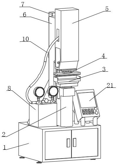
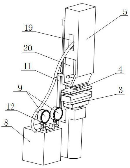
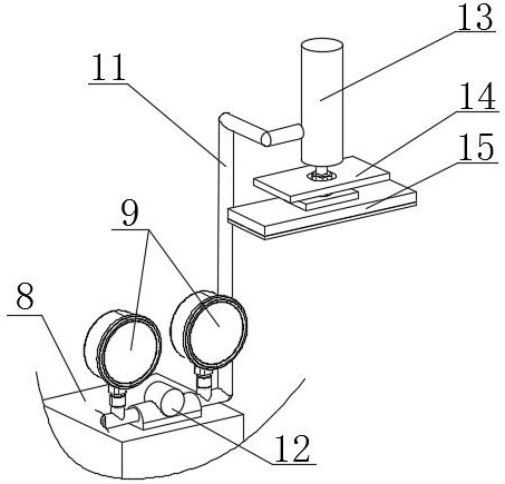
[0036] A kind of intelligent stamping equipment and stamping method for auto parts, such as Figure 1-Figure 8 As shown, it includes a stamping base 1, a stamping support 2 is installed near the center of the surface of the stamping base 1 near the front, and a stamping power box 8 is installed on the surface of the stamping base 1 and near the left end of the stamping support 2. A stamping control box 21 is installed on the surface and near the right end fron...


PUM


Abstract

The invention relates to the technical field of intelligent stamping equipment, and discloses intelligent stamping equipment and a stamping method for automobile parts. The intelligent stamping equipment comprises a stamping base, wherein a stamping support is installed at the position, close to the front, of the center of the surface of the stamping base, a stamping power box is installed at the position, close to the left end of the stamping support, of the surface of the stamping base, and a stamping control box is installed at the position, close to the front of the right end of the stamping support, of the surface of the stamping base. According to the intelligent stamping equipment and the stamping method for the automobile parts, an executing part, a second stamping assembly and a first stamping assembly are arranged, so that the stamping of the automobile parts is operated step by step, the stamping process is further detailed, the stamping effect is guaranteed, the problem that the height size of a formed sheet metal part structure is not uniform due to the fact that a sheet metal plate and a punch are asymmetrically placed is solved, and the stability of the equipment during stamping machining is improved through the cooperation of the executing part and a stamping head.

Description

technical field [0001] The invention relates to the technical field of intelligent stamping equipment, in particular to an intelligent stamping equipment and a stamping method for auto parts. Background technique [0002] Sheet metal is a comprehensive cold working process for thin metal plates (usually below 6mm), including shearing, punching / cutting / compositing, folding, welding, riveting, splicing, forming (such as automobile body), etc. Its distinctive feature is the same The thickness of the parts is the same, and the products processed by the sheet metal process are called sheet metal parts. The sheet metal parts referred to by different industries are generally different, and they are mostly used for assembly. Sheet metal stamping processing mainly includes blanking, fitter, drawing holes, Punching machine (stamping bending, punching, corner cutting, blanking, etc.), bending and other basic processes, there are many sheet metal materials suitable for stamping processi...

Claims


Application Information

Patent Timeline
IPC IPC(8): B21D22/02B21D43/00B21D55/00F16F15/08
CPCB21D22/02B21D43/003B21D55/00F16F15/08
Inventor 邵志英
Owner 十堰帝尔科技有限公司
Why Eureka
Try Eureka