Hinge punching equipment for furniture door installation

A technology for installation and furniture doors. It is applied in the direction of drilling/drilling equipment, metal processing equipment, positioning devices, etc. It can solve the problems of cumbersome feeding and positioning, and prone to danger, so as to ensure the quality of punching and improve punching. efficiency effect

Pending Publication Date: 2021-09-03
王瑞
View PDF0 Cites 2 Cited by
  • Summary
  • Abstract
  • Description
  • Claims
  • Application Information

AI Technical Summary

Problems solved by technology

[0004] In order to overcome the disadvantages of cumbersome feeding and positioning, and prone to danger, the technical problem of the present invention is to provide a hinge punching equipment for furniture door installation that is convenient for feeding and positioning and is safe.

Method used


Image

  • Hinge punching equipment for furniture door installation
  • Hinge punching equipment for furniture door installation
  • Hinge punching equipment for furniture door installation

Examples


Embodiment 1

[0067] A hinge punching equipment for furniture door installation, such as figure 1 As shown, it includes a mounting table 1, a first mounting frame 2, a cylinder 3, a push rod 4, a drill bit 5, a placement mechanism 6 and a rotating mechanism 7, and the rear side of the top of the mounting table 1 is provided with a first mounting frame 2. The frame 2 is provided with a cylinder 3, the output end of the cylinder 3 is provided with a push rod 4, the bottom of the push rod 4 is provided with a drill bit 5, the middle of the mounting table 1 top is provided with a rotating mechanism 7, and the top of the rotating mechanism 7 is provided with a placement mechanism 6.

[0068] The worker places the hinge to be punched in the placing mechanism 6, makes the placing mechanism 6 fix the hinge, and then starts the cylinder 3 to work, and the cylinder 3 drives the drill bit 5 to move downward through the push rod 4, thereby punching the hinge. When the cylinder 3 drives the drill bit 5 ...

Embodiment 2

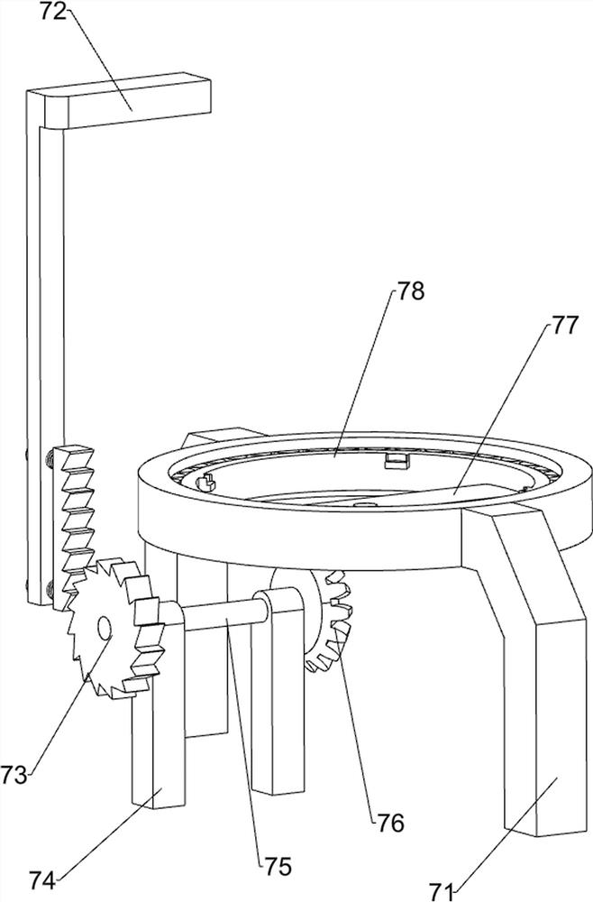
[0070] On the basis of Example 1, such as Figure 2-3As shown, the rotating mechanism 7 includes a second mounting bracket 71, a first connecting rod 72, a ratchet ratchet assembly 73, a first mounting block 74, a second connecting rod 75, a bevel gear set 76, a first connecting plate 77 and a column Bearing 78, a second mounting frame 71 is provided in the middle of the top of the mounting table 1, a first connecting rod 72 is provided on the left side of the push rod 4, and the first connecting rod 72 is provided with two first mounting blocks 74 in the middle of the top of the mounting table 1, A second connecting rod 75 is rotatably provided between the two first mounting blocks 74, and a ratchet ratchet assembly 73 is provided on the left side of the second connecting rod 75 and the first connecting rod 72, and the ratchet ratchet assembly 73 is formed by the ratchet ratchet Composition, the ratchet is connected on the left side of the second connecting rod 75, the ratche...

Embodiment 3

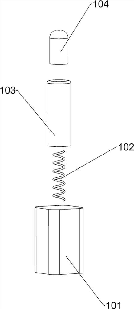
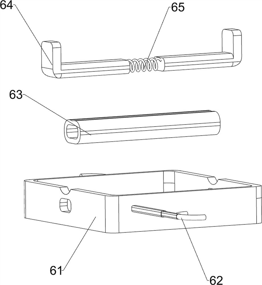
[0074] On the basis of Example 2, such as Figure 4-7 As shown, a clamping mechanism 8 is also included, and the clamping mechanism 8 includes a second connecting plate 81, a fixed block 82, a first telescopic rod 83, a second spring 84, a second sleeve 85, and a second clamping block 86 , inclined sleeve 87, the third spring 88 and the third connecting rod 89, the second mounting bracket 71 top rear side is provided with a second connecting plate 81, the second connecting plate 81 is provided with a fixed block 82, and the fixed block 82 is provided with There is a second sleeve 85, and the sliding type in the second sleeve 85 is provided with two first telescopic rods 83, a second spring 84 is arranged between the first telescopic rods 83, and a second spring 84 is arranged on the first telescopic rods 83. The clamping block 86 and the second clamping block 86 are all slidably connected with the second connecting plate 81, and the top of the second clamping block 86 is place...


PUM


Abstract

The invention relates to hinge punching equipment, in particular to hinge punching equipment for furniture door installation, and provides the hinge punching equipment which is used for furniture door installation, is convenient in feeding and positioning and is safe. The hinge punching equipment for furniture door installation comprises an installation table used for installing the whole equipment, a first installation frame arranged on one side of the top of the installation table, an air cylinder arranged on the first installation frame, a push rod arranged at the output end of the air cylinder, a drill bit arranged at the bottom of the push rod, a rotating mechanism arranged in the middle of the top of the installation table, and a placing mechanism arranged at the top of the rotating mechanism. Through cooperation of the rotating mechanism and the placing mechanism, when the push rod moves upwards, the rotating mechanism is driven to drive the placing mechanism and the hinge to rotate, when the push rod moves downwards, the rotating mechanism does not drive the placing mechanism and the hinge to rotate, the hinge is punched through the drill rod, and the punching efficiency is improved.

Description

technical field [0001] The invention relates to a hinge punching device, in particular to a hinge punching device for furniture door installation. Background technique [0002] Hinge is also known as hinge, and its official name is hinge. Often composed of two folds, it is a part that connects two parts of an object and enables it to move. Ordinary hinges are used for cabinet doors, windows, etc.; the materials are iron, copper and stainless steel. The thickness of the leaves of ordinary hinges is 1-3 mm. In the process of hole opening, the ordinary hinges often use punching. However, the feeding and positioning of ordinary punching devices are more cumbersome when punching. The work efficiency is low, and when positioning, the staff often need to manually adjust the position of the hinge to be punched, which is close to the punching die, which is prone to danger. [0003] Therefore, we need to propose a hinge punching device that is convenient for feeding and positioning...

Claims


Application Information

Patent Timeline
Patent Type & Authority Applications(China)
IPC IPC(8): B23B39/16B23B41/00B23Q3/06
CPCB23B39/161B23B41/00B23Q3/062
Inventor 王瑞
Owner 王瑞
Why Eureka
Try Eureka