
Landing retracting and releasing mechanism for small unmanned aerial vehicle

A technology of small unmanned aerial vehicle and retractable mechanism, applied in the direction of arrester hook, etc., can solve the problems of blocking failure, damage, low system reliability, etc., and achieve the effect of avoiding impact load and reliable mechanism connection

Active Publication Date: 2021-09-03
SHENYANG AIRCRAFT DESIGN INST AVIATION IND CORP OF CHINA
View PDF5 Cites 0 Cited by
  • Summary
  • Abstract
  • Description
  • Claims
  • Application Information

AI Technical Summary

Problems solved by technology

In the existing arresting hook mechanism using the first method, the arresting hook will bounce after the arresting hook is in place, which has the risk of arresting failure; the arresting hook in the second method can solve the problem of the first method because the arresting position is controllable. However, the structure of the existing arresting hook in the second mode is complicated, and the single-acting cylinder of its operating mechanism cannot meet the high load bearing capacity, and its hook arm cannot rotate at the same time, so when the aircraft lands and hooks After the arresting wire, its asymmetric hook wire state will cause damage to the aircraft structure, and the system reliability is low

Method used


Image

  • Landing retracting and releasing mechanism for small unmanned aerial vehicle
  • Landing retracting and releasing mechanism for small unmanned aerial vehicle
  • Landing retracting and releasing mechanism for small unmanned aerial vehicle

Examples


Embodiment Construction

[0026] In order to make the purpose, technical solution and advantages of the application more clear, the technical solution in the embodiment of the application will be described in more detail below in conjunction with the drawings in the embodiment of the application. In the drawings, the same or similar reference numerals denote the same or similar elements or elements having the same or similar functions throughout. The described embodiments are some, but not all, embodiments of the application. The embodiments described below by referring to the figures are exemplary, and are intended to explain the present application, and should not be construed as limiting the present application. Based on the embodiments in this application, all other embodiments obtained by persons of ordinary skill in the art without creative efforts fall within the protection scope of this application. Embodiments of the present application will be described in detail below in conjunction with th...


PUM


Abstract

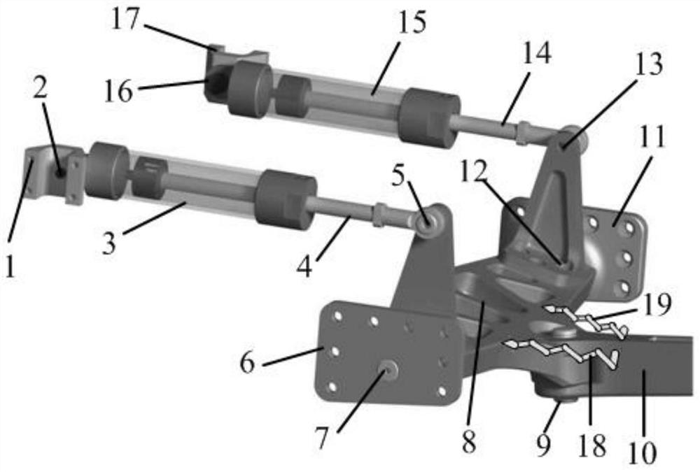
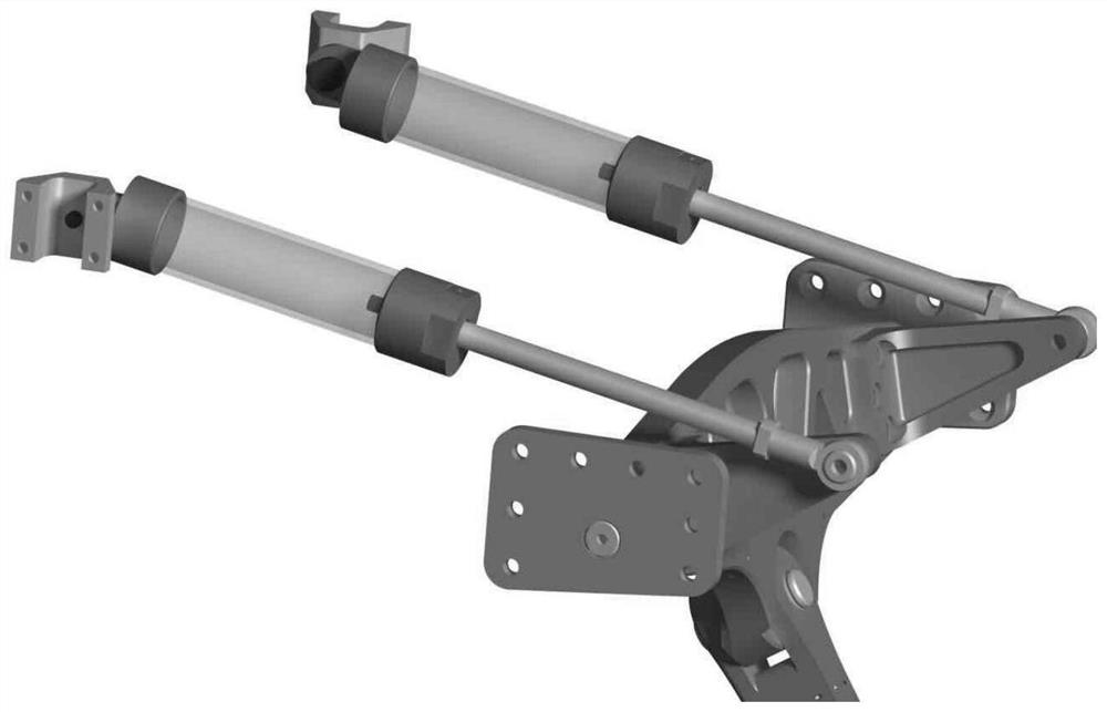
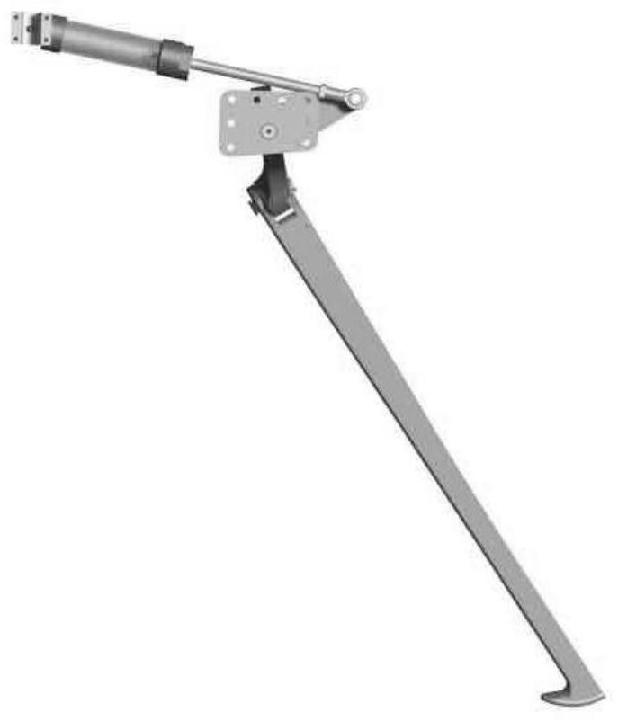
The invention belongs to the technical field of aircraft manufacturing, and particularly relates to a landing retracting and releasing mechanism for a small unmanned aerial vehicle. A first actuating cylinder base and a second actuating cylinder base are respectively arranged on the machine body; the upper end of the first actuating cylinder is mounted on a first actuating cylinder base, a first telescopic rod is arranged on the first actuating cylinder, the upper end of the second actuating cylinder is mounted on a second actuating cylinder base, and a second telescopic rod is arranged on the second actuating cylinder; the first turntable base and the second turntable base are respectively mounted on the machine body; one side of the arresting hook rotating disc is mounted on the first rotating disc base, the other side of the arresting hook rotating disc is mounted on the second rotating disc base, a first upper connecting part and a second upper connecting part are arranged on the arresting hook rotating disc, the first upper connecting part is connected with the first telescopic rod, the second upper connecting part is connected with the second telescopic rod, and a lower connecting part is further arranged on the arresting hook rotating disc; and the arresting hook is connected with the lower connecting part of the arresting hook turntable. The arresting hook can be stably and automatically folded and unfolded.

Description

technical field [0001] The application belongs to the technical field of aircraft manufacturing, and in particular relates to a landing retractable mechanism for a small unmanned aerial vehicle. Background technique [0002] During the landing process of the taxiing take-off and landing UAV, in order to reduce the taxiing distance of the UAV, an arresting hook device is usually used to achieve a short-distance arrest, and the arresting cable is hooked when landing. There are generally two types of traditional taxiing and landing arresting hook systems: one is that the arresting hook mechanism is installed on the aircraft body and does not retract during flight and landing; the other is that the arresting hook mechanism is installed on the aircraft body and Stow up during flight and down during landing. The first type of arresting hook mechanism that is not retractable exposes the arresting hook during flight, which will lead to increased flight resistance and is not conveni...

Claims


Application Information

Patent Timeline
Patent Type & Authority Applications(China)
IPC IPC(8): B64C25/68
CPCB64C25/68Y02T50/40
Inventor 梁磊肖静詹光
Owner SHENYANG AIRCRAFT DESIGN INST AVIATION IND CORP OF CHINA
Learn More