Quick-change sealed vacuum suction head structure design

A technology of structural design and vacuum suction head, which is applied in the direction of labeling, packaging, labeling machines, etc., can solve the problems of complicated suction head replacement operation and reduced air tightness, and achieve easy operation, improved replacement time, and increased extrusion The effect of strength

Pending Publication Date: 2021-09-03
常州鼎毅电子科技有限公司
View PDF0 Cites 1 Cited by
  • Summary
  • Abstract
  • Description
  • Claims
  • Application Information

AI Technical Summary

Problems solved by technology

[0006] The invention provides a structural design of a quick-change sealed vacuum suction head, which solves the problem that the air-tightness will be reduced due to repeated replacement of the existing suction head, and the replacement operation of the suction head is complicated.

Method used


Image

  • Quick-change sealed vacuum suction head structure design
  • Quick-change sealed vacuum suction head structure design
  • Quick-change sealed vacuum suction head structure design

Examples


no. 1 example

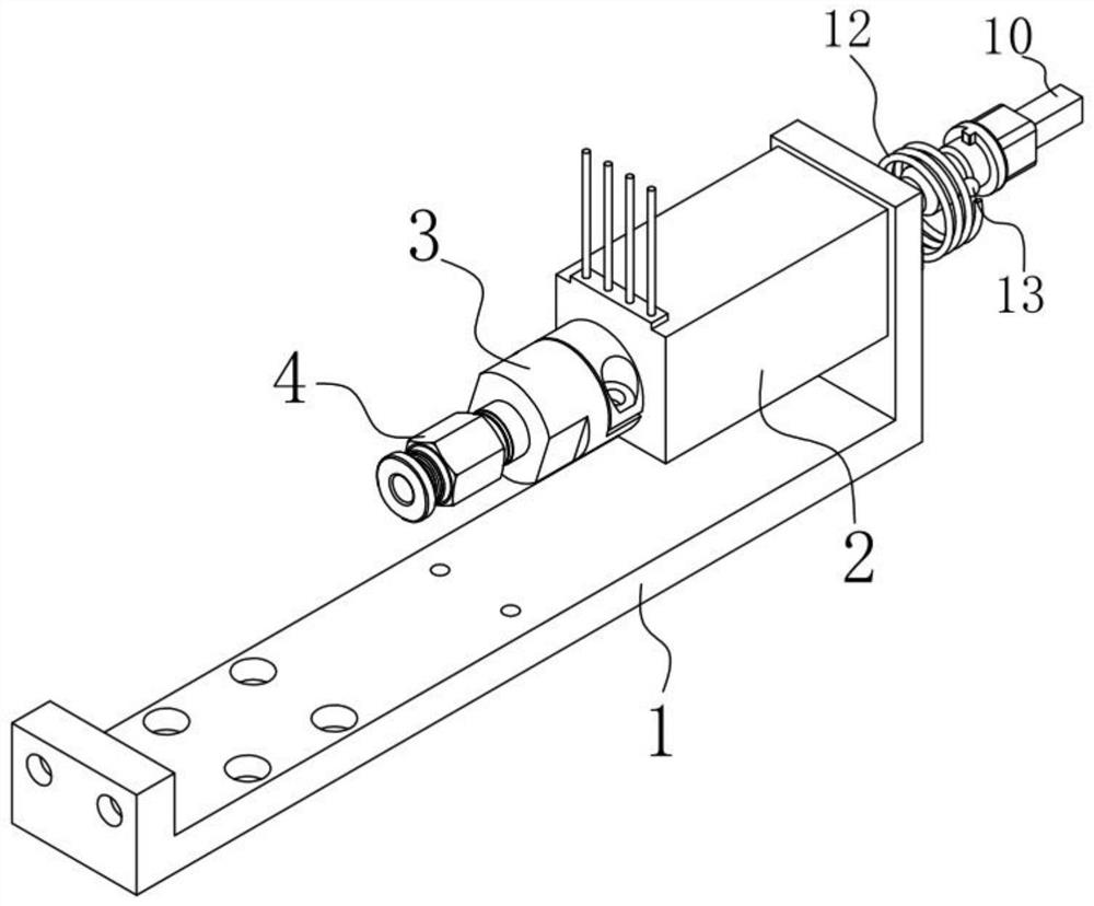
[0040] Please refer to figure 1 , figure 2 , image 3 , Figure 4 , Figure 5 and Figure 6 ,in, figure 1 A structural schematic diagram of the first embodiment of the structural design of a quick-change sealed vacuum suction head provided by the present invention; figure 2 for figure 1 A sectional view of the whole of the device shown; image 3 for figure 2 The partial structural schematic diagram of the whole device shown in Fig. 4 is figure 1 A schematic diagram of the overall three-dimensional structure of the device shown; Figure 5 for figure 1 The schematic diagram of the structure of the lower motor connection sleeve shown; Figure 6 for figure 1 Overall side view of the device shown. A structural design of a quick-change sealed vacuum suction head, comprising: a mounting bracket 1;

[0041] A rotating electrical machine 2, the rotating electrical machine 2 is fixedly installed on one side of the mounting bracket 1;

[0042] A universal quick-change ...

no. 2 example

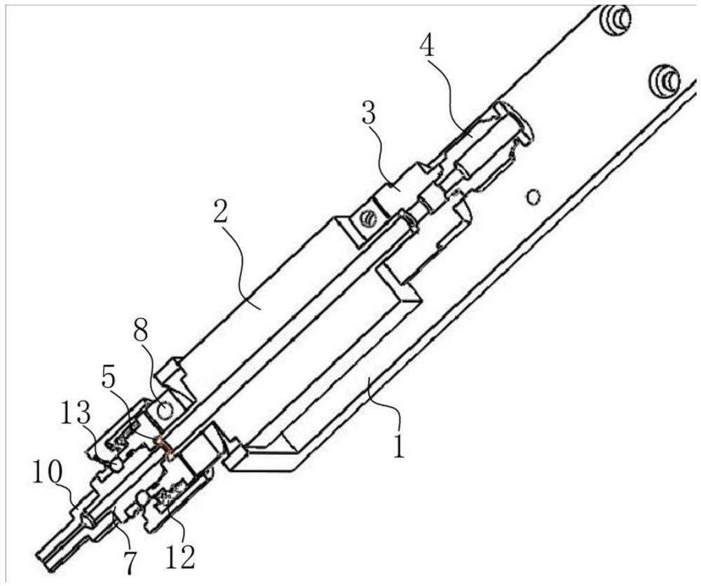
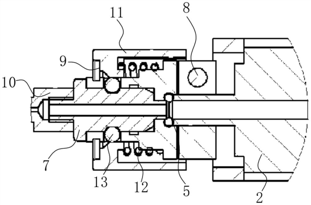
[0058] Please refer to Figure 7 , Figure 8 , Figure 9 , Figure 10 , Figure 11 and Figure 12 , based on the structural design of the quick-change sealing vacuum suction head provided in the first embodiment of the present application, the second embodiment of the present application proposes another structural design of the quick-change sealing vacuum suction head. The second embodiment is only a preferred mode of the first embodiment, and the implementation of the second embodiment will not affect the independent implementation of the first embodiment.

[0059] Specifically, the structural design of a quick-change sealed vacuum suction head provided by the second embodiment of the present application is different in that, in a structural design of a quick-change sealed vacuum suction head, the surface of the lower motor connection sleeve 6 is provided with The connection assembly 14 , the connection assembly 14 includes a rotating seat 141 , and a fixed sleeve 142 i...


PUM


Abstract

The invention provides a quick-change sealing vacuum suction head structure design. The quick-change sealing vacuum suction head structure design comprises an installation support a rotary motor is fixedly installed on one side of the installation support, a universal quick-change connector is arranged at one end of the rotary motor, a suction head is arranged at one end of the universal quick-change connector, a first spring is arranged on the surface of the universal quick-change connector in a sleeving mode, clamping balls are arranged in the universal quick-change connector, an elastic clamping sleeve is arranged on the surface of the universal quick-change connector in a sleeving mode, and a clamping bead is arranged in the elastic clamping sleeve. According to the quick-change sealing vacuum suction head structure design, the first spring is arranged at one end of the rotating motor and matched with the elastic clamping sleeve to drive an existing suction head to be connected, the operation steps can be simplified, the suction head replacement time can be shortened, the clamping balls are arranged on the surface of the universal quick-change connector and used in cooperation with the elastic clamping sleeve so that the limiting effect can be achieved, and the clamping bead is arranged in the elastic clamping sleeve so as to be conveniently matched with the the clamping balls in the universal quick-change connector to block the elastic clamping sleeve.

Description

technical field [0001] The invention relates to the field of mechanical automation, in particular to a structural design of a quick-change sealed vacuum suction head. Background technique [0002] Mechanical automation: Automation refers to the process in which a machine or device is automatically operated or controlled according to a predetermined program or instruction without human intervention, and mechanical automation is the process in which a machine or device is automatically controlled by mechanical means. [0003] At present, when labeling rigid circuit boards in mechanical automation, it needs to be assisted by sealing vacuum suction heads. [0004] Existing sealed vacuum suction heads need to be replaced during use, but repeated replacement of suction heads for a long time will reduce the sealing performance of the connection of the suction heads, and the existing device will Can cause operation steps to be complicated, and operation time is long. [0005] Ther...

Claims


Application Information

Patent Timeline
Patent Type & Authority Applications(China)
IPC IPC(8): B65C9/00B65C9/14
CPCB65C9/00B65C9/14
Inventor 吴海斌
Owner 常州鼎毅电子科技有限公司
Why Eureka
Try Eureka