Switch cabinet operating environment improving system and method

A technology of operating environment and switchgear, which is applied in the direction of control/regulation system, panel/switch station circuit device, substation/switch layout details, etc., which can solve the problem of insufficient air circulation in switchgear, no temperature adjustment effect, and equipment insulation effects To achieve obvious dehumidification effect, prolong equipment replacement time, and ensure normal operation

Active Publication Date: 2019-11-12
STATE GRID CHONGQING ELECTRIC POWER +1
View PDF13 Cites 3 Cited by
  • Summary
  • Abstract
  • Description
  • Claims
  • Application Information

AI Technical Summary

Problems solved by technology

[0008] 1. Install a dehumidifier or air conditioner in the switch room: installing air conditioners, exhaust fans or mobile cabinet dehumidifiers in the switch room can only improve the ambient air humidity conditions in the switch room, and have little effect on the temperature and humidity in the cabinet
[0009] 2. The switchgear is sealed and sealed with glue: generally, a sealing strip is installed on the door of the switchgear to seal the bottom of the cable room of the switchgear and strengthen the sealing of the switchgear, but the humidity in the air inside the cabinet will also affect the The insulation of the equipment is affected, and there is no temperature regulation effect
[0010] 3. Increase the ventilation holes on the top of the cabinet: by increasing the ventilation holes, the sufficient circulation of the air inside and outside the switchgear cannot be satisfied, so the effect of increasing the ventilation holes is limited

Method used


Image

  • Switch cabinet operating environment improving system and method
  • Switch cabinet operating environment improving system and method
  • Switch cabinet operating environment improving system and method

Examples


Embodiment 2

[0066] The structure of each part of embodiment 2 can refer to embodiment 1

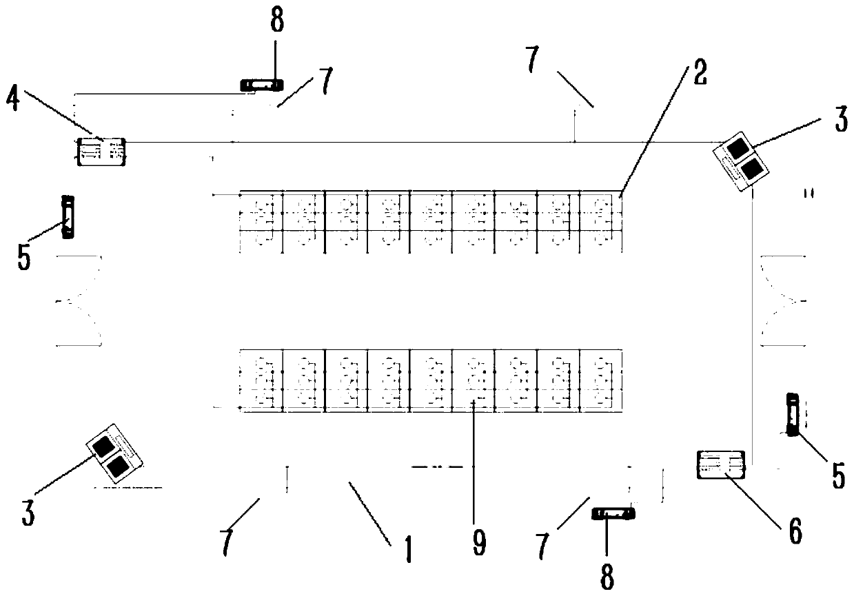
[0067] A system for improving the operating environment of a switchgear, comprising a switchgear 2, an axial flow fan 9, shutters 7, an industrial constant temperature dehumidifier 3, and a temperature and humidity sensor.

[0068] The switchgear 2 is arranged in the switch room 1 with better airtightness, and the industrial constant temperature dehumidifier 3 can be arranged at any position in the switch room 1, and the air can be taken in from the four sides and the top. The specific size of the room is determined, so that the air on different planes in the switch cabinet 2 can be processed by the constant temperature industrial dehumidifier 3. The air outlet of the industrial constant temperature dehumidifier 3 is at the bottom, and any position of the switch room 1 is arranged to test the indoor temperature of the switch room 1. A number of indoor temperature and humidity sensors 5 for humidity, ...


PUM


Abstract

The invention provides a switch cabinet operating environment improving system and method. The system comprises a switch cabinet, an axial flow fan, an industrial constant temperature dehumidifier, and temperature and humidity sensors, wherein the switch cabinet is arranged in a closed switch room; the axial flow fan is mounted on a pressure relief plate on the top of the switch cabinet; the axialflow fan is in signal connection with a controller in the switch room; the switch room is also internally provided with the industrial constant temperature dehumidifier and the temperature and humidity sensor for detecting the switch cabinet; the temperature and humidity sensor that detects air temperature and humidity is arranged outside the switch room; and the industrial dehumidifier and the temperature and humidity sensors inside and outside the switch room are in signal connection with the control system. The air in the switch cabinet is ensured to be dry, and insulation flashover and insulation damage of the equipment in the switch cabinet are reduced.

Description

technical field [0001] The invention belongs to the technical field of electrical insulation protection, and in particular relates to an environment optimization system and method for a switch cabinet. Background technique [0002] Insulation breakdown (insulation breakdown): It refers to the complete loss of insulation ability when the insulator is damp or subjected to excessive voltage. [0003] Insulation flashover: refers to the discharge phenomenon that occurs on the surface of the insulation structure or in the air in contact with the electrode under the action of an electric field before the breakdown of the insulation structure occurs. [0004] High-voltage switchgear is the most widely used and most numerous switchgear. Because there are different degrees of problems in design, manufacture, installation and operation and maintenance, the accident rate is relatively high. Among the switchgear accidents of many natures, insulation accidents mostly occur at voltage l...

Claims


Application Information

Patent Timeline
Patent Type & Authority Applications(China)
IPC IPC(8): H02B1/30H02B1/28H02B1/56H02B1/24G05D27/02
CPCG05D27/02H02B1/24H02B1/28H02B1/306H02B1/565
Inventor 徐郁由铭甫李宗成刘明军赵登攀夏维建张鹏举
Owner STATE GRID CHONGQING ELECTRIC POWER
Why Eureka
Try Eureka