
Novel sawing machine blade connection structure and manufacturing method thereof

A technology of connecting structure and saw blade, which is applied in the direction of tool manufacturing, manufacturing tools, metal sawing equipment, etc. of sawing machine devices, can solve the problems of increased production cost, increased vibration of sawing machine, consumption of spare parts, etc., and achieves easy installation and disassembly. , The effect of reducing the chance of turbulence and saving replacement time

Pending Publication Date: 2017-09-05
UNIV OF SCI & TECH LIAONING
View PDF5 Cites 3 Cited by
  • Summary
  • Abstract
  • Description
  • Claims
  • Application Information

AI Technical Summary

Problems solved by technology

Especially in the case of a large impact during the sawing process of the saw machine, for example: when the size of the billet to be sawed is relatively large, or the hardness of the billet material is relatively high, the vibration of the saw machine will also increase accordingly; this will lead to wear and tear on the saw teeth of the saw blade The speed is increased, the replacement cycle of the saw blade is shortened, which is not conducive to the continuous production of the production line
[0003] In addition, due to the high-speed operation of the saw blade and the relatively large impact load, the journal where the saw blade is installed on the saw disc is often worn, resulting in irregular rotation of the saw blade due to unreliable fixation. Shorten the service life of spare parts such as saw blades and saw discs, and seriously affect the sawing speed and sawing quality
Therefore, once the journal of the saw disc is worn, it needs to be replaced in time. Generally, it takes about 5 hours, which not only affects the continuity of production, but also causes a large consumption of spare parts and increases production costs.

Method used


Image

  • Novel sawing machine blade connection structure and manufacturing method thereof
  • Novel sawing machine blade connection structure and manufacturing method thereof
  • Novel sawing machine blade connection structure and manufacturing method thereof

Examples


Embodiment Construction

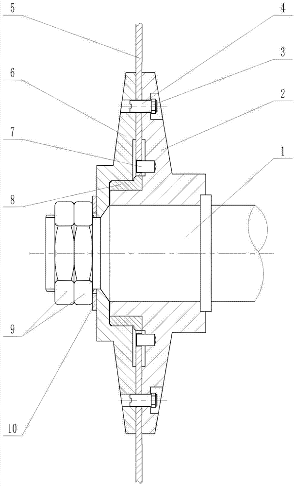
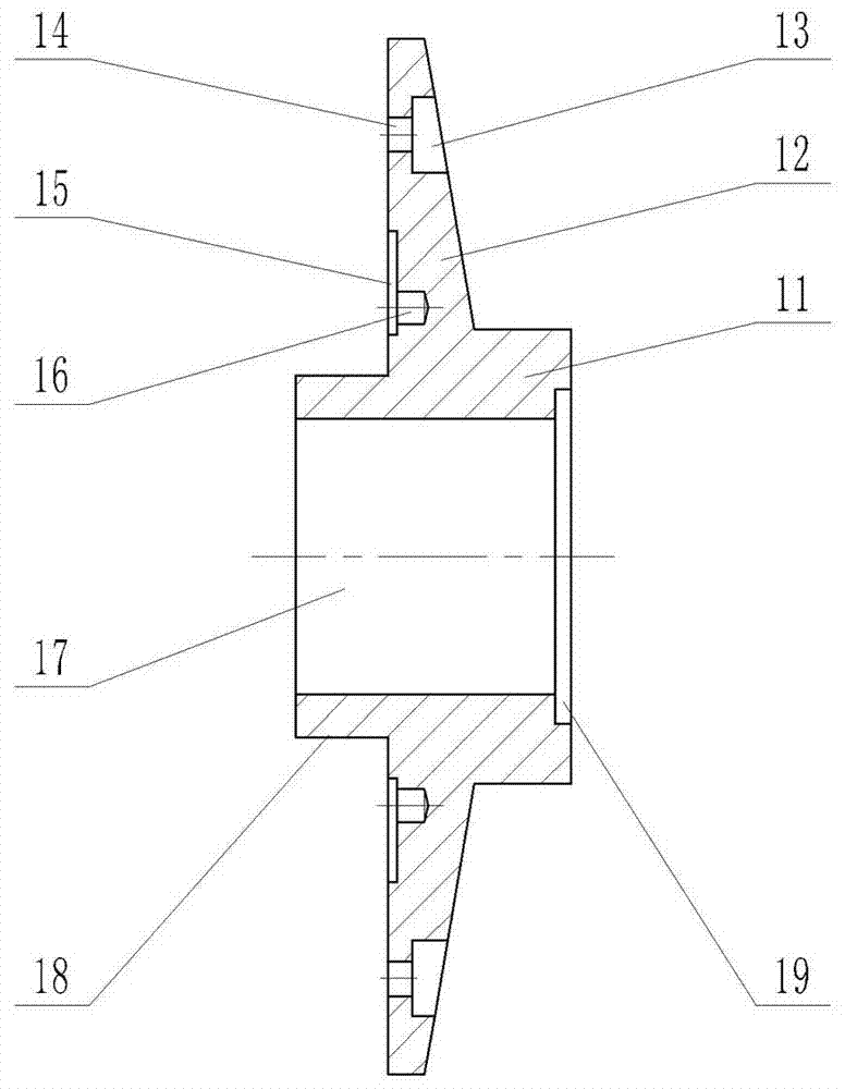
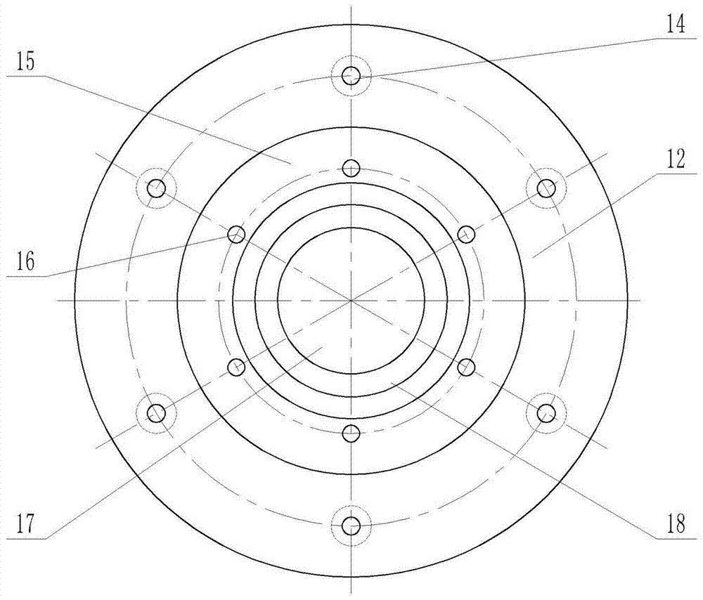
[0026] according to Figure 1-7The specific structure of the present invention will be described in detail. This novel saw blade connecting structure includes a saw disc arranged on the main shaft 1 of the saw machine for connecting the saw blade 5 of the fixed saw machine, wherein the saw disc consists of the main saw disc 2 fixed on the main shaft 1 of the saw machine and the The dismantled auxiliary saw disc 6 constitutes. The main saw disc 2 is composed of a cylindrical main disc body 11, and the middle part of the main disc body 11 is provided with a main shaft connecting through hole 17 arranged along the axis; There is a saw disc journal 18 for mounting the journal bushing 8 . On the outer wall of the main saw disc 2 main disc body 11, a disc-shaped main fixed disc 12 for fastening the saw blade 5 of the saw machine is also provided; the main fixed disc 12 is provided with six bolts arranged at equal intervals along the same circumference Through hole 14. Moreover, ...


PUM


Abstract

The invention discloses a novel sawing machine blade connection structure and a manufacturing method thereof and aims at solving the problems that the blade is not firmly fixed, and spare parts, such as a saw plate are short in service life and poor in production continuity. The novel sawing machine blade connection structure comprises a saw plate arranged on a main shaft of a sawing machine; the novel sawing machine blade connection structure is characterized in that the saw plate comprises a man saw plate and an auxiliary saw plate; the main saw plate is arranged on the main shaft of the sawing machine through a main shaft connection through hole; a shaft neck shaft sleeve is arranged on a saw plate shaft neck of the main saw plate; the auxiliary saw plate is connected with the shaft neck shaft sleeve arranged on the saw plate shaft neck of the main saw plate through a shaft sleeve sink hole; a sawing machine blade is arranged between the main saw plate and the auxiliary saw plate; and is arranged on a saw plate installation flange of the shaft neck shaft sleeve through as blade installation hole; and the manufacturing method of the connection structure comprises manufacturing of the main saw plate, the auxiliary saw plate and the shaft neck shaft sleeve, machining of the sawing machine blade and combined installation of various parts. The novel sawing machine blade connection structure is reasonable in design, connection of the blade and the saw plate can be tighter, whole set replacement is not needed when abrasion is generated, and the novel sawing machine blade connection structure is simple and convenient to maintain, high in production efficiency and low in consumption of the spare parts.

Description

technical field [0001] The invention belongs to the technical field of steel rolling production equipment, and in particular relates to a new type of saw blade connection structure for a saw machine, which is fast in replacement, easy to maintain, and can effectively improve production efficiency and reduce spare parts consumption, and its manufacture. method. Background technique [0002] At present, the saw blades of hot saw machines and cold saw machines on the domestic steel rolling production line are connected and fixed roughly as follows: the saw disc is installed on the main shaft of the saw machine, the inner hole of the saw blade and the journal of the saw disc are connected by transition fit, and the A plurality of connecting bolts uniformly distributed in the circumferential direction fix the saw blade on the disc surface of the saw disc. During the use of the saw machine, the saw blade needs to be replaced regularly due to the wear and tear of the saw teeth. E...

Claims


Application Information

Patent Timeline
Patent Type & Authority Applications(China)
IPC IPC(8): B23D61/02B23D65/00
CPCB23D61/02B23D65/00
Inventor 石加联韩冰陈东吴恩旭
Owner UNIV OF SCI & TECH LIAONING
Learn More