Belt conveyor buffer bed with adjustable groove angle
A buffer bed, belt conveyor technology, applied in conveyors, loading/unloading, non-rotational vibration suppression, etc., can solve the problems that the buffer strips cannot be matched with the tapes and cannot better protect the tapes, etc., to achieve increased volume, increased contact area effect
- Summary
- Abstract
- Description
- Claims
- Application Information
AI Technical Summary
Problems solved by technology
Method used
Image

Examples
Embodiment
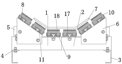
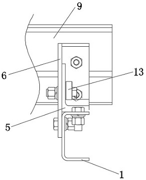
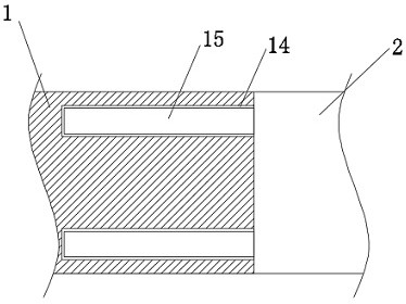
[0026] Such as Figure 1-5 As shown, the embodiment of the present invention provides a belt conveyor buffer bed with adjustable groove angle, including a first beam 1, a second beam 2, a mounting bracket 3, a mounting plate 4, an adhesive tape 7, a first buffer strip 10 and a second The buffer strip 18, the two mounting plates 4 are fixedly connected to the bottom of the first cross beam 1 and the second cross beam 2 respectively, the mounting bracket 3 and the mounting plate 4 are fixedly connected by fasteners, the first cross beam 1 and the second cross beam 2 are all equipped with a buffer bed body, the buffer bed body includes an eccentric sleeve support 5, a support plate 6 and a second buffer bar support 9, and the two support plates 6 are respectively connected to the front of the first beam 1 and the second beam 2 The surface is fixedly connected by fasteners, and the two eccentric sleeve supports 5 are respectively fixedly connected with the tops of the first beam 1...
PUM
 Abstract
Description
Claims
Application Information
PatSnap Eureka turns technology decisions into work you can execute. Powered by our Innovation Knowledge Graph, it runs expert workflows across engineering, life sciences, materials and intellectual property. Get your review-ready output in minutes.


