Take-up device for power construction

A wire take-up device and electric construction technology, which is applied in the directions of transportation and packaging, thin material handling, and filamentary material transportation, etc., can solve the problems of large cable usage, increased use cost, and a lot of manpower and material resources, and reduce labor intensity. , Improve work efficiency, improve the effect of winding efficiency

Active Publication Date: 2021-09-03
JIYANG POWER SUPPLY CO STATE GRID SHANDONG ELECTRIC POWER CO +1
View PDF7 Cites 1 Cited by
  • Summary
  • Abstract
  • Description
  • Claims
  • Application Information

AI Technical Summary

Problems solved by technology

[0003]At present, due to the large amount of cables used and the long length of use, a lot of manpower and material resources are required for each replacement. The existing power construction cable take-up devices are all It is used alone. Once multiple cables need to be collected at the same time, multiple take-up devices need to be used at the same time, which increases the cost of use and causes a waste of resources.

Method used


Image

  • Take-up device for power construction
  • Take-up device for power construction
  • Take-up device for power construction

Examples


Embodiment 1

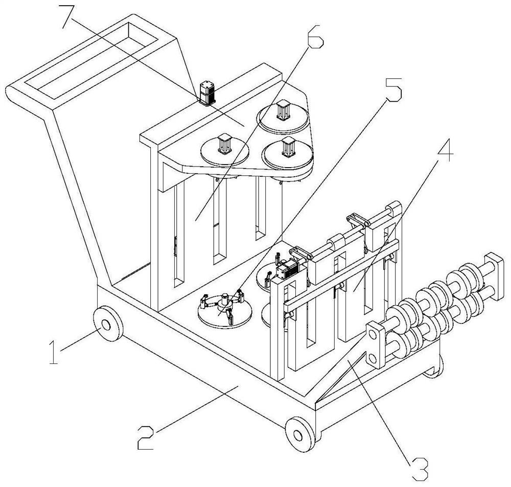
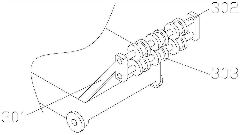
[0044] Such as Figure 1-6 , a wire take-up device for electric power construction, comprising a support plate 2, a moving wheel 1 with brake pads is installed at the bottom of the support plate 2, the support plate 2 is a cavity structure, and a The driving mechanism 8 is equipped with a rotating mechanism 5 and a guide mechanism 3 on the support plate 2. The guide mechanism 3 is installed on one end of the support plate 2. The guide mechanism 3 includes a bracket 301, a connecting shaft 302, and a guide roller 303. The bracket 301 is obliquely installed on the support plate 2, the connecting shaft 302 is provided with two, and the connecting shaft 302 is installed on the bracket 301, the guide roller 303 is provided with a plurality, and the plurality of guide rollers 303 are evenly installed on the two sides. On the two connecting shafts 302, the guide rollers 303 on the two connecting shafts 302 correspond one by one and cooperate with each other. The rotating mechanism 5 ...

Embodiment 2

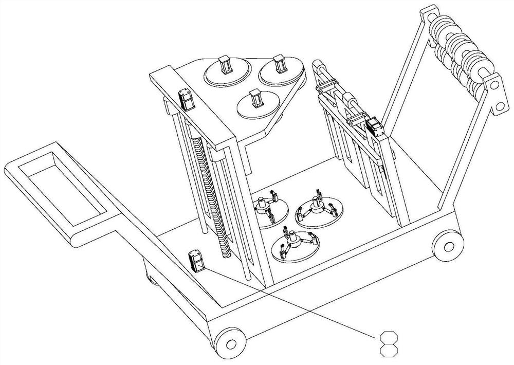
[0050] Such as Figure 7-10 , the difference from Embodiment 1 is that it also includes a lifting mechanism 6, and the lifting mechanism 6 includes a first support vertical plate 602, a support frame 606, a threaded rod 603, a motor 601, and a guide rod 604. There are three chute 605 on the plate 602, and three fixed blocks 607 are installed on the support frame 606, and the three fixed blocks 607 are arranged in the three chute 605 and extend to the outside of the chute 605, and the threaded rod 603 One end of which is installed on the middle fixed block 607 and extends to the top of the fixed block 607, the other end is installed on the support plate 2, the motor 601 is installed on the top of the first support book board, and the output shaft of the motor 601 is connected with the screw thread The rods 603 are connected, and the guide rod 604 is symmetrically installed on both sides of the threaded rod 603, and one end of the guide rod 604 is installed on the fixed block 60...

Embodiment 3

[0054] Such as Figure 11-13 , The difference from Embodiment 1 and Embodiment 2 is that it also includes a forward adjustment mechanism 4, which includes a second support vertical plate 401, a fixed frame 403, a motor 404, a connecting rod 406, and a connecting piece 405 , the fixed shaft 407, a first strip-shaped through hole 402 and a second strip-shaped through-hole 408 are provided on the second support vertical plate 401, and the first strip-shaped through-hole 402 and the second strip-shaped through-hole 408 are intersected, so The fixing frame 403 is installed in the first strip-shaped through hole 402 and the second strip-shaped through hole 408, the first strip-shaped through hole 402 is provided with a guide, and the guide is installed on the fixing frame 403. The second strip-shaped through hole 408 is provided with a mounting block 4014, the motor 404 is installed on the top end of the second support vertical plate 401, the fixed shaft 407 is installed on the outp...


PUM


Abstract

The invention discloses a take-up device for power construction. The take-up device for power construction comprises a support plate, moving wheels with brake pads are mounted at the bottom of the support plate, the support plate is of a cavity structure, a driving mechanism is mounted in the support plate, a rotating mechanism and a guide mechanism are mounted on the support plate, the guide mechanism is mounted at one end of the support plate, and the guide mechanism comprises a support, a connecting shaft and a guide roller, and the support is obliquely installed on the support plate. According to the take-up device for power construction, multiple cables can be taken up at the same time, the cable take-up efficiency is guaranteed, and meanwhile, the working efficiency is improved, the purpose of guiding the cables can be achieved through the arrangement of the guide mechanism, and the purpose of separating multiple wires can be achieved, the wires are prevented from being wound together in the take-up process, the take-up efficiency is greatly improved, and the driving mechanism provides power for the rotating mechanism, the rotating mechanism can drive a wire take-up roller to rotate, the wire take-up purpose is achieved, the labor intensity of workers is greatly reduced, and the wire take-up quality is guaranteed.

Description

technical field [0001] The invention belongs to the technical field of electric power equipment, and in particular relates to a wire take-up device for electric power construction. Background technique [0002] A cable is made of one or more mutually insulated conductors and an outer insulating protective layer. It is a wire that transmits power or information from one place to another. It is usually a similar rope twisted by several or several groups of wires. Each group of wires is insulated from each other, and is often twisted around a center, and the entire outside is covered with a highly insulating covering. Cables have the characteristics of internal electrification and external insulation. Cables include power cables, control cables, compensation cables, shielded cables, high-temperature cables, computer cables, signal cables, coaxial cables, fire-resistant cables, marine cables, mine cables, and aluminum alloy cables. etc. [0003] At present, due to the large am...

Claims


Application Information

Patent Timeline
IPC IPC(8): B65H54/553B65H54/44B65H54/28B65H57/14B65H57/28B65H54/72
CPCB65H54/553B65H54/44B65H54/28B65H57/14B65H57/28B65H54/72B65H2701/34
Inventor 张文露高国梁张文惠李连河张绍新李明孙善朋陈玉宝
Owner JIYANG POWER SUPPLY CO STATE GRID SHANDONG ELECTRIC POWER CO
Why Eureka
Try Eureka