Hoisting equipment

A technology of lifting equipment and rotating shaft, which is applied in the direction of load hanging components, safety devices, hoisting devices, etc., and can solve problems such as difficulty in lifting the main exhaust pipe

Pending Publication Date: 2021-09-03
BEIJING TIANRUN CONSTR +1
View PDF5 Cites 0 Cited by
  • Summary
  • Abstract
  • Description
  • Claims
  • Application Information

AI Technical Summary

Problems solved by technology

[0004] The purpose of the present invention is to provide a lifting device that can solve the problem of difficulty in lift

Method used

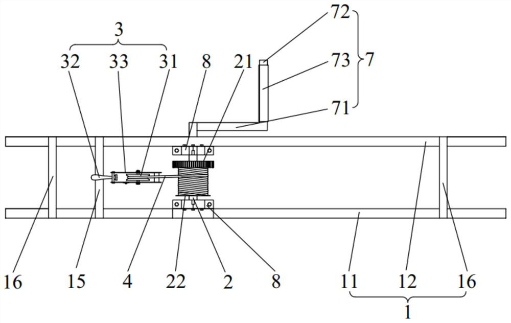
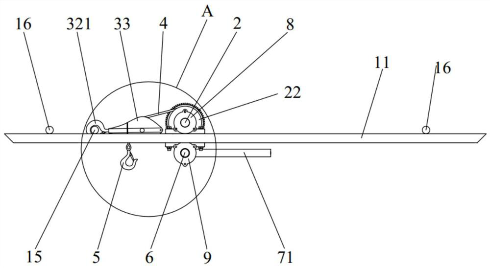
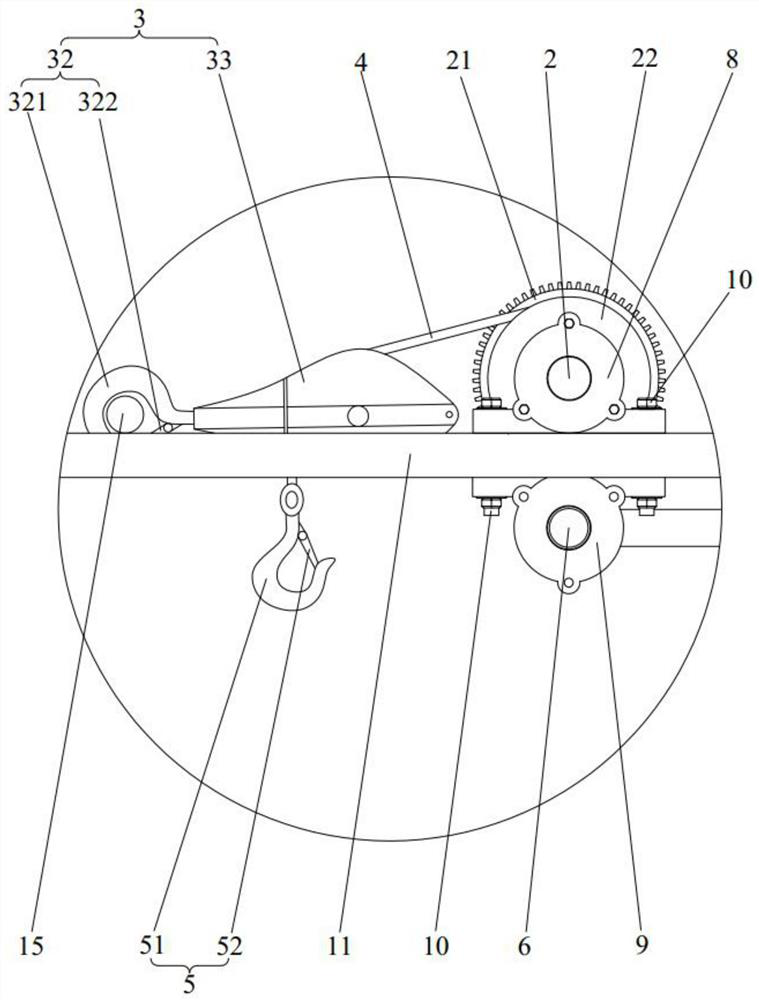

Image

  • Hoisting equipment
  • Hoisting equipment
  • Hoisting equipment

Examples


Embodiment Construction

[0036] The present invention will be further described in detail below in conjunction with the accompanying drawings and embodiments. It should be understood that the specific embodiments described here are only used to explain the present invention, but not to limit the present invention. In addition, it should be noted that, for the convenience of description, only some structures related to the present invention are shown in the drawings but not all structures.

[0037] In the description of the present invention, unless otherwise clearly specified and limited, the terms "connected", "connected" and "fixed" should be understood in a broad sense, for example, it can be a fixed connection, a detachable connection, or an integrated ; It can be a mechanical connection or an electrical connection; it can be a direct connection or an indirect connection through an intermediary, and it can be the internal communication of two components or the interaction relationship between two ...


PUM


Abstract

The invention belongs to the technical field of building construction, and discloses hoisting equipment. The hoisting equipment comprises a supporting bracket, a first rotating shaft, a pulley assembly and a traction rope, the supporting bracket comprises a first supporting rod and a second supporting rod which are arranged at an interval, and the pulley assembly is arranged on the supporting bracket and comprises a fixed pulley. The first rotating shaft can rotate relative to the first supporting rod and the second supporting rod, the traction rope can be wound on the first rotating shaft by rotating the first rotating shaft, or the traction rope is gradually led out from the first rotating shaft, and the leading-out end of the traction rope bypasses the fixed pulley and is connected with a lifting hook assembly. When a main exhaust pipe is installed, the hoisting equipment is placed on the upper floor of the floor where the main exhaust pipe to be installed is located, the supporting bracket and the wall face form a triangle, the first rotating shaft is rotated, the lifting hook assembly is placed downwards, the lifting hook assembly is hooked to the main exhaust pipe to be installed, then lifting is conducted, the problem that the main exhaust pipe is difficult to lift in the limited space is effectively solved, and construction materials are prevented from being damaged.

Description

technical field [0001] The invention relates to the technical field of building construction, in particular to a lifting device. Background technique [0002] In the construction of construction projects, many equipment and materials need to be installed in a confined space, which greatly increases the difficulty of construction. Especially the equipment installation in the vertical direction, such as the installation of building exhaust pipes, the installation of on-board pump pipes during the concrete pouring construction stage, the installation of the standpipes of fire water pipes, etc., due to the narrow operable space during installation, it is difficult for construction personnel It brings great inconvenience, low construction efficiency, and the installation quality of the equipment in these positions is often poor after installation. [0003] Taking the installation of building exhaust pipes as an example, there are reserved holes on the floor for passing through t...

Claims


Application Information

Patent Timeline
IPC IPC(8): B66C1/36B66C15/00B66C13/08B66D1/04B66D1/12B66D1/36
CPCB66C1/36B66C15/00B66C13/08B66D1/04B66D1/12B66D1/36
Inventor 刘世显李盼盼高旭孙冬冬孙卓
Owner BEIJING TIANRUN CONSTR
Why Eureka
Try Eureka