
Hydraulic bidirectional jar

A jar, hydraulic technology, applied in wellbore/well components, earthwork drilling and other directions, can solve the problems of the length of the jar, the weakening of the jar release force, and the stuck, etc., to shorten the length of the whole machine, The effect of simplifying the structure

Pending Publication Date: 2021-09-03
四川伟创石油装备制造有限公司 +1
View PDF0 Cites 0 Cited by
  • Summary
  • Abstract
  • Description
  • Claims
  • Application Information

AI Technical Summary

Problems solved by technology

[0003] Jars are generally divided into two types: mechanical and hydraulic. The mechanical jar needs to increase the tensile or compressive force to a preset force value before releasing it. The preset force value cannot be adjusted after the tool enters the well. The size of the shock force is constant, but due to the wear and tear of the mechanism and friction pairs, the shock release force will gradually weaken
There may be two disadvantages during on-site use: one is that after a long time of use, the release force of the shock is weakened, and false shocks occur; the other is that the stretching or compression force transmitted to the jar is not enough to start the shock
[0004] The hydraulic jar achieves the purpose of jarring and releasing the impact by suppressing the pressure in the oil chamber and then releasing the pressure suddenly. The commonly used full hydraulic drilling jar has a complicated structure and is generally divided into upper and lower oil chambers. , using two sets of cone-type flow-limiting valve groups to control the upper and lower strokes respectively. After use, the cone valve group and the outer shell are often locked and stuck, and the jar is also very long, which is not conducive to safety control. , in order to solve the above problems, the present invention provides a hydraulic two-way jar

Method used


Image

  • Hydraulic bidirectional jar
  • Hydraulic bidirectional jar
  • Hydraulic bidirectional jar

Examples


Embodiment Construction

[0031] The following will clearly and completely describe the technical solutions in the embodiments of the present invention with reference to the accompanying drawings in the embodiments of the present invention. Obviously, the described embodiments are only some, not all, embodiments of the present invention. Based on the embodiments of the present invention, all other embodiments obtained by persons of ordinary skill in the art without making creative efforts belong to the protection scope of the present invention.

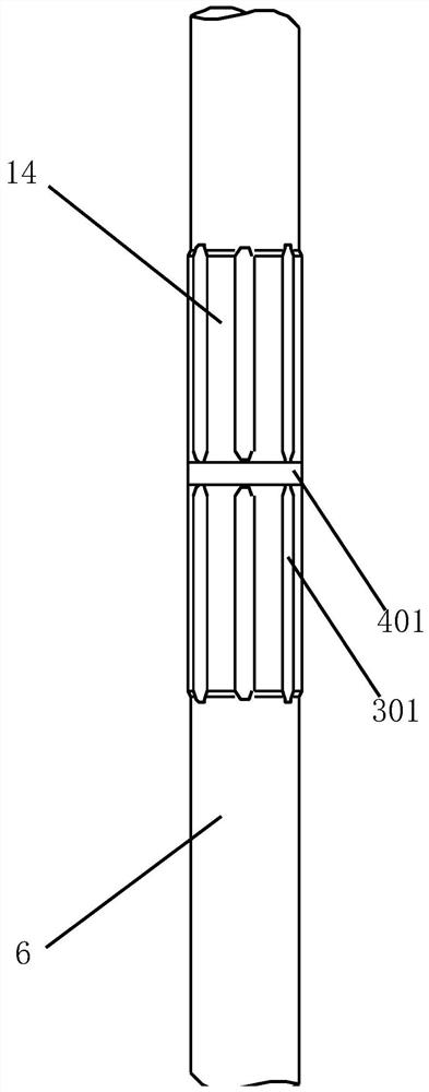
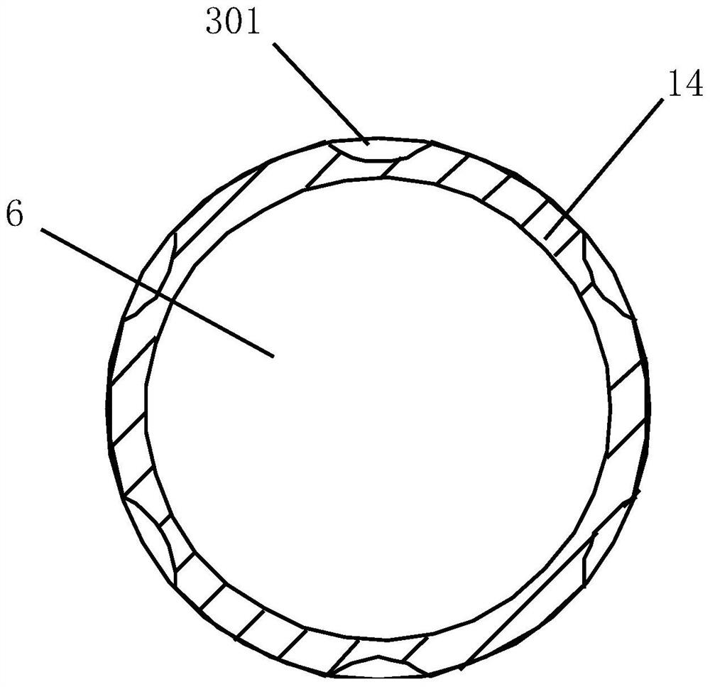
[0032] see Figure 1-11 , a hydraulic two-way jar, characterized in that it includes a mandrel 1, a spline sleeve 2, an upper pressure body 3, a lower pressure body 4, a lower joint 5 and an extension shaft 6, and the bottom end of the spline sleeve 2 is threaded. There is an upper pressure body 3, the bottom end of the upper pressure body 3 is threaded with a lower pressure body 4, the bottom end of the lower pressure body 4 is threaded with a lower joint 5, ...


PUM


Abstract

The invention relates to the technical field of petroleum and geological drilling equipment, in particular to a hydraulic bidirectional jar. The technical problems that a cone valve set and an outer shell are locked and clamped, the whole jar is too long, and safety control is not facilitated are to be solved. In order to solve the technical problems, the invention provides the hydraulic bidirectional jar. The hydraulic bidirectional jar mainly comprises a mandrel, a spline housing, an upper pressure body, a lower pressure body, a lower joint and an extension shaft. According to the hydraulic bidirectional jar, upper jarring and lower jarring are integrated, and the upper jarring and the lower jarring are arranged in the same oil cavity through a set of flow-limiting valves, so that the structure is greatly simplified, the whole machine length is shortened, and the bidirectional jar can work in a full-pull-open or full-compression state when jarring does not need to be started through mutual cooperation of a pressure relief groove, a reset oil hole and a pressure building oil hole; jarring cannot be started as long as the bidirectional jar is not in the reset state, so that the bidirectional jar can be used as a jar while drilling, and the purpose of starting jarring when work while drilling is needed is achieved.

Description

technical field [0001] The invention relates to the technical field of petroleum and geological drilling equipment, in particular to a hydraulic two-way jar. Background technique [0002] At present, when dealing with drilling sticking accidents, jars are often used to help release the jamming. The jars are installed above the stuck points. When stretching or compressing the drill string at the wellhead, the jars are first in the In the locked state, this process forces the upper drill string to undergo elastic deformation. When the elastic potential energy is stored sufficiently or the storage time reaches a certain length of time, the jar will be released suddenly. At this moment, all the elastic potential energy of the drill string will suddenly hit the card. Click to unlock the card. [0003] Jars are generally divided into two types: mechanical and hydraulic. The mechanical jar needs to increase the tensile or compressive force to a preset force value before releasing ...

Claims


Application Information

Patent Timeline
IPC IPC(8): E21B31/00E21B31/113
CPCE21B31/005E21B31/113
Inventor 胡波王岳张祥陈云
Owner 四川伟创石油装备制造有限公司
Learn More