High-strength connecting structure and sectional type wind power blade

A technology for connecting structures and wind power blades, which is applied in the direction of connecting components, wind power generation, and wind power engines consistent with the wind direction. Service life, effect of ensuring connection strength and sealing

Active Publication Date: 2021-09-03
CHANGZHOU HONGFA ZONGHENG ADVANCED MATERIAL TECH
View PDF11 Cites 2 Cited by
  • Summary
  • Abstract
  • Description
  • Claims
  • Application Information

AI Technical Summary

Problems solved by technology

[0004] In the prior art, there are some segmented wind power blades, and bolts are used to connect the segments, but the bolts are usually set inside the wind power blades, and it is necessary to drill holes in the wind power blades, and tighten and fix the bolts from the holes. After drilling holes along the contour direction of the wind turbine blade, it will affect the structural strength of the wind turbine blade, thereby affecting the service life of the wind turbine blade

Method used


Image

  • High-strength connecting structure and sectional type wind power blade
  • High-strength connecting structure and sectional type wind power blade
  • High-strength connecting structure and sectional type wind power blade

Examples


Embodiment 1

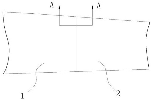
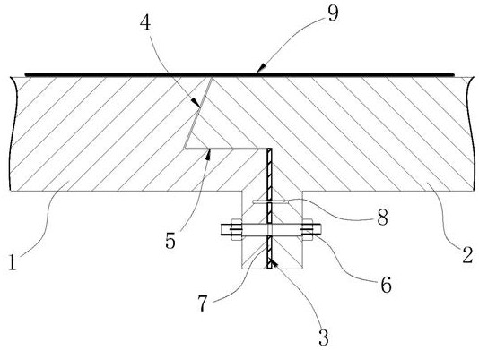
[0049] Such as Figures 1 to 3 Shown: a high-strength connection structure, including:

[0050] The first segment 1 and the second segment 2 arranged along the length direction of the wind power blade, the first segment 1 and the second segment 2 include:

[0051] A first mating surface 3 extending toward the inside of the wind power blade, the first mating surface 3 being perpendicular to the length direction of the wind power blade;

[0052] A second mating surface 4 that is misaligned with the first mating surface 3, and the second mating surface 4 is misaligned in a direction close to the first segment 1 with respect to the first mating surface 3;

[0053] A connection surface 5, the connection surface 5 connects the first mating surface 3 and the second mating surface 4;

[0054] Connecting bolts 6, the connecting bolts 6 are located in the wind power blades, and pass through the two first mating surfaces 3 to fix the first segment 1 and the second segment 2, and the co...

Embodiment 2

[0069] Such as Figures 4 to 7 Shown: The difference from Embodiment 1 is that the second mating surface 4 of the second segment 2 is provided with a bump 21, and the second mating surface 4 of the first segment 1 is correspondingly provided with a groove, and the bump 21 and the concave The slots cooperate with each other to limit the flanging of the second segment 2 to the outside of the wind turbine blade.

[0070] In this embodiment, the anti-flange structure is a protrusion 21 and a groove that cooperate with each other. By setting the protrusion 21 on the second segment 2, the first segment 1 is correspondingly provided with a groove. In the first segment 1 When docking with the second segment 2, the protrusion 21 is inserted into the groove, so that the groove limits the degree of freedom of the protrusion 21, restricts its flipping and movement perpendicular to the length direction of the wind turbine blade, thereby restricting the second segment Segment 2 is flanged ...
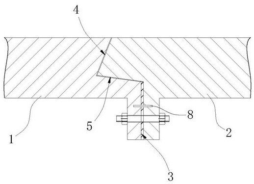
Embodiment 3

[0073] Such as Figures 8 to 9 Shown: The difference from Example 1 is that the second segment 2 is provided with a pre-embedded screw sleeve 31 on the connecting surface 5, the embedded screw sleeve 31 is located at one end close to the second mating surface 4, and the embedded screw sleeve 31 is vertical In the length direction of the wind turbine blade, the first segment 1 is provided with a corresponding through hole on the connecting surface 5, and a locking bolt 32 is arranged in the through hole, and the locking bolt 32 cooperates with the embedded screw sleeve 31 to restrict the second segment 2. Flanging to the outside of the wind turbine blade.

[0074] In this embodiment, the anti-flange structure is a pre-embedded screw sleeve 31 and a locking bolt 32 that cooperate with each other. By setting the embedded screw sleeve 31 on the connecting surface 5 of the second segment 2, the first segment 1 The connecting surface 5 of the connecting surface 5 is provided with a...


PUM


Abstract

The invention relates to the technical field of wind power blades, in particular to a high-strength connecting structure and a sectional type wind power blade. The high-strength connecting structure comprises a first section and a second section which are arranged in the length direction of the wind power blade, and the first section and the second section comprise first matching faces, second matching faces, connecting faces and connecting bolts; the first matching faces extend towards the interior of the wind power blade, and the first matching faces are perpendicular to the length direction of the wind power blade; the second matching faces and the first matching faces are staggered, and the second matching faces are staggered in the direction close to the first section relative to the first matching faces; the connecting faces are connected with the first matching faces and the second matching faces; the connecting bolts are located in the wind power blade and penetrate through the two first matching faces to fix the first section and the second section, and the connecting bolts are parallel to the length direction of the wind power blade; and an anti-flanging structure is arranged between the first section and the second section, and the anti-flanging structure limits the second section from being flanged towards the outer side of the wind power blade. According to the high-strength connecting structure and the sectional type wind power blade, the connecting strength and the sealing performance are guaranteed, and the service life of the wind power blade is prolonged.

Description

technical field [0001] The invention relates to the technical field of wind power blades, in particular to a high-strength connection structure and segmented wind power blades. Background technique [0002] The use of a large amount of fossil energy has not only promoted the development of technology, but also increased the burden on the earth's ecological environment. Air pollution threatens human life and health. Renewable energy has gradually become the preferred energy source and occupies an increasingly important position in the energy structure of various countries. status. As a form of renewable energy, wind energy has the advantages of low development cost, mature technology, and wide distribution, and has become a key direction for the development of renewable energy in recent years. [0003] In order to make full use of wind energy resources, wind turbines are also gradually becoming larger, and the length of their blades is also increasing. The areas rich in wind...

Claims


Application Information

Patent Timeline
Patent Type & Authority Applications(China)
IPC IPC(8): F03D1/06F16B13/10
CPCF03D1/0675F16B13/04Y02E10/72
Inventor 谈昆伦季小强白高宇
Owner CHANGZHOU HONGFA ZONGHENG ADVANCED MATERIAL TECH
Why Eureka
Try Eureka