Arrangement and operation mode of wind driven generators at top of power plant boiler

A technology for wind turbines and boiler tops, which is applied to wind turbines that are consistent with the wind direction, wind turbines, and wind turbines that are at right angles to the wind direction to achieve the effects of improving stability, reducing emissions, and reducing wear and tear.

Pending Publication Date: 2021-09-03
XI AN JIAOTONG UNIV
View PDF6 Cites 0 Cited by
  • Summary
  • Abstract
  • Description
  • Claims
  • Application Information

AI Technical Summary

Problems solved by technology

[0004] Aiming at the problem that the current power plant has not yet used the height advantage of the building to generate electricity through conventional wind power, the present invention provides an arrangement and operation mode of the wind power generator on the top of the power plant boiler, and its purpose is to use the height advantage of the power plant building to wind power generation, and the electricity generated by wind power generation is directly sent to the power grid through the power transmission and transformation system of the power plant, saving the cost of building towers and power transmission facilities, and saving land and land acquisition costs, improving the economic benefits of the power plant

Method used


Image

  • Arrangement and operation mode of wind driven generators at top of power plant boiler
  • Arrangement and operation mode of wind driven generators at top of power plant boiler

Examples


Embodiment Construction

[0020] The present invention will be described in further detail below in conjunction with the accompanying drawings and specific embodiments, so that the advantages and features of the present invention can be more easily understood by those skilled in the art, so as to define the protection scope of the present invention more clearly.

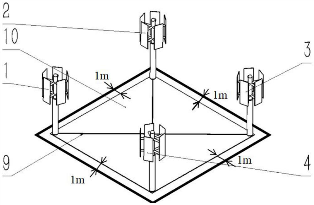
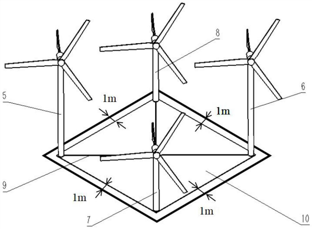
[0021] The present invention relates to the arrangement and operation mode of wind power generators on the top of boilers in power plants, including H-type wind power generators a1, H-type wind power generators b2, H-type wind power generators c3, H-type wind power generators d4, and No. 1 Y wind power generators. Type wind generator a5, No. 1 Y-type wind generator b6, No. 2 Y-type wind generator a7, No. 2 Y-type wind generator b8, transmission line 9 and the roof 10 of the boiler house of the coal-fired power plant.

[0022] The layout plan of the H-type wind power generator includes: H-type wind power generator a1, H-type wind power generato...


PUM


Abstract

The invention discloses an arrangement and operation mode of wind driven generators at the top of a power plant boiler. The arrangement and operation mode comprises four H-shaped wind driven generators, two first Y-shaped wind driven generators, two second Y-shaped wind driven generators, power transmission lines and a boiler plant roof; the arrangement scheme of the H-shaped wind driven generators comprises the H-shaped wind driven generators, the power transmission lines and the boiler plant roof; the arrangement scheme of the Y-shaped wind driven generators comprises the first Y-shaped wind driven generators, the second Y-shaped wind driven generators, the power transmission lines and the boiler plant roof; and all the wind driven generators are directly installed on the boiler plant roof and connected through the power transmission lines. According to the arrangement scheme of the two wind driven generators, the height advantage of the power plant boiler is utilized, a too high tower is not needed, strong wind energy at the high position is converted into electric energy, the generated electric energy can be directly connected into a power grid through a power transmission and transformation system of the power plant, and the economical efficiency of the power plant is greatly improved.

Description

technical field [0001] The invention belongs to the field of wind power generation, and particularly relates to an arrangement and operation mode of a wind power generator on the top of a boiler in a power plant, which is only applicable to a power plant with a relatively high boiler building, and the roof of the boiler factory building is square. Background technique [0002] Wind energy is a clean and pollution-free renewable energy. The use of wind power to generate electricity is very environmentally friendly, and the wind energy has a huge reserve, which has been increasingly valued by countries all over the world. However, due to the instability of wind power generation, it is difficult to fully utilize wind energy, which has led to wind abandonment in some areas of our country. Seriously, how to efficiently and fully utilize wind energy plays a very important role in the development of renewable and clean energy in my country. [0003] Power plants are generally far aw...

Claims


Application Information

Patent Timeline
Patent Type & Authority Applications(China)
IPC IPC(8): F03D9/25F03D1/02F03D3/02F03D9/45F03D80/00
CPCF03D3/005F03D3/02F03D1/02F03D9/255F03D9/45F03D80/00Y02E10/74Y02E10/728Y02E10/72Y02B10/30
Inventor 张梓睿刘明吴东垠
Owner XI AN JIAOTONG UNIV
Why Eureka
Try Eureka