
Radio frequency calibration device for chip testing and calibration method thereof

A technology of radio frequency calibration and chip testing, which is applied in the field of radio frequency measurement, can solve problems such as non-elimination, large system errors, and unsatisfactory effects, and achieve the effect of reducing system errors and reducing production costs

Active Publication Date: 2021-09-03
广东利扬芯片测试股份有限公司
View PDF7 Cites 1 Cited by
  • Summary
  • Abstract
  • Description
  • Claims
  • Application Information

AI Technical Summary

Problems solved by technology

However, in the existing calibration method, because the external cables of the instrument are all coaxial cables, the level of calibration can only reach the level of the test machine interface to the load board (LoadBoard)
It does not take into account the influence of the performance of the RF traces, fixtures and probes in the carrier board on the RF path, especially the large difference in the standing wave ratio of the probe at different frequencies has a great impact on the accuracy of the test. Influence
In this regard, in the test of some high-end RF chips, it is often necessary to use higher-end supporting boards and probes to reduce the impact, but the effect is not ideal, and the large and unpredictable system errors caused by the system have not been eliminated, and The test cost caused by the replacement of high-end test equipment is still very large

Method used


Image

  • Radio frequency calibration device for chip testing and calibration method thereof
  • Radio frequency calibration device for chip testing and calibration method thereof
  • Radio frequency calibration device for chip testing and calibration method thereof

Examples


Embodiment Construction

[0031] In order to describe the technical content and structural features of the present invention in detail, further description will be given below in conjunction with the implementation and accompanying drawings.

[0032] In the description of the present invention, it should be understood that the orientation or positional relationship indicated by the terms "upper", "lower", "inner", "outer" and the like are based on the orientation or positional relationship shown in the accompanying drawings, and are only intended to It is convenient to describe the present invention and simplify the description, so it should not be construed as limiting the protection content of the present invention.

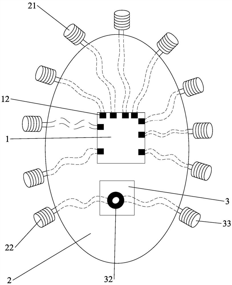
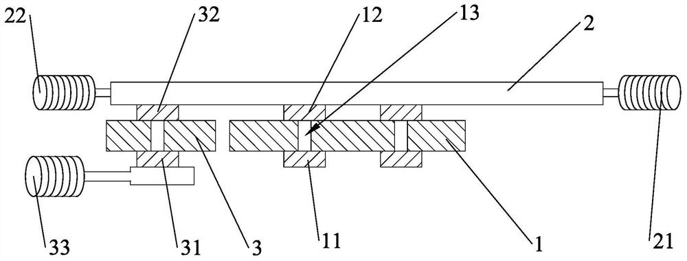
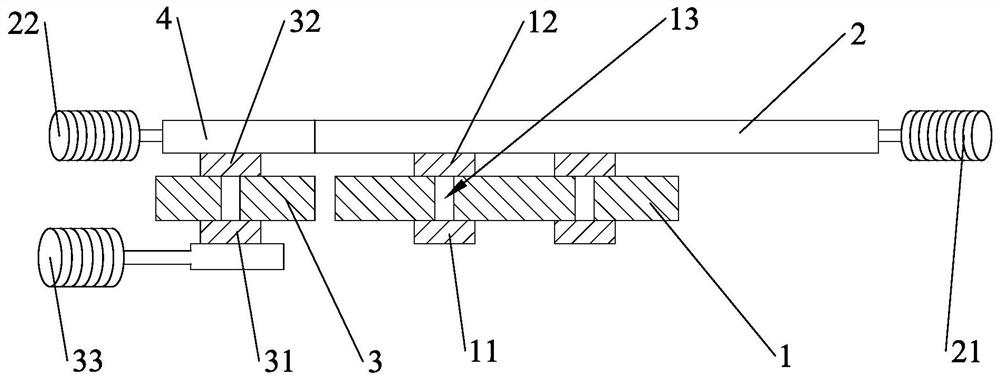
[0033] see figure 1 and figure 2 , the present invention provides a radio frequency calibration device for chip testing, used to measure the calibration value between the testing machine and the probe, which includes a first substrate 1 and a first circuit board 2 . The first substra...


PUM


Abstract

The invention discloses a radio frequency calibration device for chip testing and a calibration method thereof, which are used for measuring a calibration value between a testing machine and a probe, and the radio frequency calibration device comprises a first substrate and a first circuit board. The first substrate comprises a plurality of first lower contact discs and a plurality of first upper contact discs which are correspondingly conducted with the plurality of first lower contact discs, and the plurality of first lower contact discs are configured to make contact with the probes correspondingly. The plurality of first upper contact discs are welded on the first circuit board, the first circuit board is provided with a plurality of first test interfaces, the plurality of first test interfaces are electrically connected with the plurality of first upper contact discs respectively, and the plurality of first test interfaces are configured to be connected with a test machine or a test instrument. According to the radio frequency calibration device, measurement can be completed by adopting a simple structure, the manufacturing cost is effectively reduced, and system errors can also be reduced.

Description

technical field [0001] The invention relates to the technical field of radio frequency measurement, in particular to a radio frequency calibration device for chip testing and a calibration method thereof. Background technique [0002] Usually, before the test of the radio frequency chip, the radio frequency path needs to be calibrated. However, in the existing calibration method, because the external cables of the instrument are all coaxial cables, the level of calibration can only reach the level from the test machine interface to the load board (LoadBoard). It does not take into account the influence of the performance of the RF traces, fixtures and probes in the carrier board on the RF path, especially the large difference in the standing wave ratio of the probe at different frequencies has a great impact on the accuracy of the test. influences. In this regard, in the test of some high-end RF chips, it is often necessary to use higher-end supporting boards and probes to...

Claims


Application Information

Patent Timeline
IPC IPC(8): G01R35/00
CPCG01R35/005Y02D30/70
Inventor 康承乾陈谷颖卢旭坤袁俊辜诗涛
Owner 广东利扬芯片测试股份有限公司
Learn More