Bulk acoustic wave resonator and manufacturing method thereof

Active Publication Date: 2021-09-03
HANGZHOU XINGHE TECH CO LTD
View PDF15 Cites 6 Cited by
  • Summary
  • Abstract
  • Description
  • Claims
  • Application Information

AI Technical Summary

Problems solved by technology

[0008] The current preparation method of air-gap FBAR cavity will cause a series of problems in the process, especially the release process, such as the collapse of the deposited film on the upper part of the cavity due to poor mechanical stability, energy loss caused by uneven stress distribution of the film layer or tympanic membrane, etc. The problem will greatly reduce the performance of the device or even damage the device
Moreover, most of the new frequency bands of 5G are high-frequency bands above 2.5GHz. In high-frequency bands, the electrode thickness and piezoelectric film thickness of the resonator will be further thinned, and the film stress will be more difficult due to the release of the sacrificial layer during cavity preparation. control, resulting in degraded resonator performance, lower yield, or reliability issues
[0009] With the popularization of 5G frequency bands, the performance requirements of filter devices are higher, and the piezoelectric film doping process has been adopted on a large scale, such as AlN film doped with scandium Sc element (Scandium). The stress becomes larger and more difficult to control, requiring better control of the cavity release process to control the film stress and achieve better resonator performance

Method used


Image

  • Bulk acoustic wave resonator and manufacturing method thereof
  • Bulk acoustic wave resonator and manufacturing method thereof
  • Bulk acoustic wave resonator and manufacturing method thereof

Examples


Embodiment Construction

[0042] The application will be further described in detail below in conjunction with the accompanying drawings and embodiments. It should be understood that the specific embodiments described here are only used to explain related inventions, rather than to limit the invention. It should also be noted that, for the convenience of description, only the parts related to the related invention are shown in the drawings.

[0043] It should be noted that, in the case of no conflict, the embodiments in the present application and the features in the embodiments can be combined with each other. The present application will be described in detail below with reference to the accompanying drawings and embodiments.

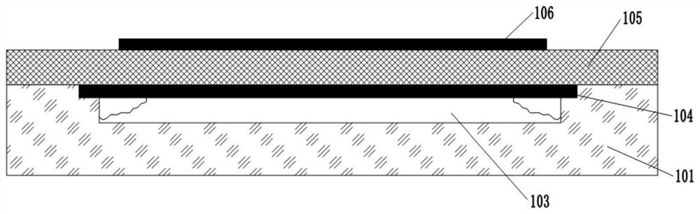
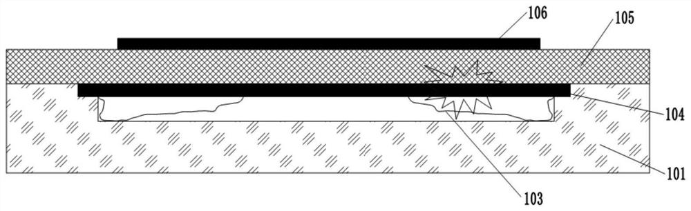
[0044] Figure 1a -b shows a schematic diagram of the release of the sacrificial layer of the BAW resonator in the prior art. like Figure 1a and 1b As shown, the cavity of the bulk acoustic wave resonator of this structure and the release channel are in the same plane, bec...


PUM

PropertyMeasurementUnit
thicknessaaaaaaaaaa
thicknessaaaaaaaaaa
thicknessaaaaaaaaaa

Abstract

The invention discloses a bulk acoustic wave resonator, which comprises a substrate and a resonance function layer arranged on the substrate, the resonance function layer and the substrate surround to form a resonant cavity, the resonance function layer comprises a bottom electrode layer, a piezoelectric layer and a top electrode layer which are sequentially formed on the substrate, and the bulk acoustic wave resonator also comprises a release cavity formed at the periphery of the resonant cavity, the release cavity and the resonant cavity are located in different planes and communicate in a staggered mode. The invention also discloses a manufacturing method for the bulk acoustic wave resonator, which comprises the following steps: manufacturing one or more grooves on the surface of the substrate, depositing a sacrificial material to fill the grooves, forming a sacrificial layer at least covering the surface of the substrate between the grooves and part of the grooves on the surface of the substrate, and sequentially forming the bottom electrode, the piezoelectric layer and the top electrode layer, and releasing the sacrificial material by utilizing the release liquid medicine to pass through the piezoelectric layer from the uncovered area of the bottom electrode layer to reach the release hole at the corresponding position of the groove. The problem of stress sudden change in the sacrificial layer release process is avoided, and the stability of the cavity structure and the consistency of the resonance performance of the device are remarkably improved.

Description

technical field [0001] The present application relates to the field of communication devices, and mainly relates to a bulk acoustic wave resonator and a manufacturing method thereof. Background technique [0002] With the increasingly crowded electromagnetic spectrum, the continuous increase of frequency bands and functions of wireless communication equipment, and the rapid growth of wireless communication electromagnetic spectrum from 500MHz to above 5GHz, people are demanding RF front-end modules with high performance, low cost, low power consumption, and small size. demand is increasing day by day. As one of the RF front-end modules, the filter has the function of improving the transmitted and received signals, and plays a pivotal role in the RF front-end module. FBAR (Thin film bulk acoustic cresonator) is a bulk acoustic wave resonator. It is a filter composed of multiple FBARs connected in a topological network structure. Strong and other characteristics to meet the ...

Claims


Application Information

Patent Timeline
Patent Type & Authority Applications(China)
IPC IPC(8): H03H9/17H03H3/02H03H9/02
CPCH03H9/173H03H9/02015H03H3/02H03H2003/023
Inventor 李林萍盛荆浩江舟
Owner HANGZHOU XINGHE TECH CO LTD
Why Eureka
Try Eureka