Antenna apparatus

A technology for antenna devices and electrical appliances, applied in directions such as antennas, antenna supports/installation devices, and antenna parts, etc., can solve the problems of power consumption and heat generation hindering the reduction of weight and size, and improve interchangeability and applicability. Improved assembly performance and effective heat dissipation design

Pending Publication Date: 2021-09-03
KMW INC
View PDF0 Cites 0 Cited by
  • Summary
  • Abstract
  • Description
  • Claims
  • Application Information

AI Technical Summary

Problems solved by technology

Even so, due to the rental cost of the installation site or space constraints, it is necessary to make radio frequency components (Antenna / Filter / Power Amplifier / Transceiver etc.) Expansion requires high output, and due to this high output, power consumption and heat generation will hinder weight and size reduction

Method used


Image

  • Antenna apparatus
  • Antenna apparatus
  • Antenna apparatus

Examples


Embodiment Construction

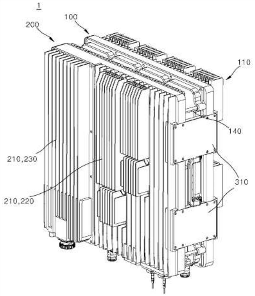
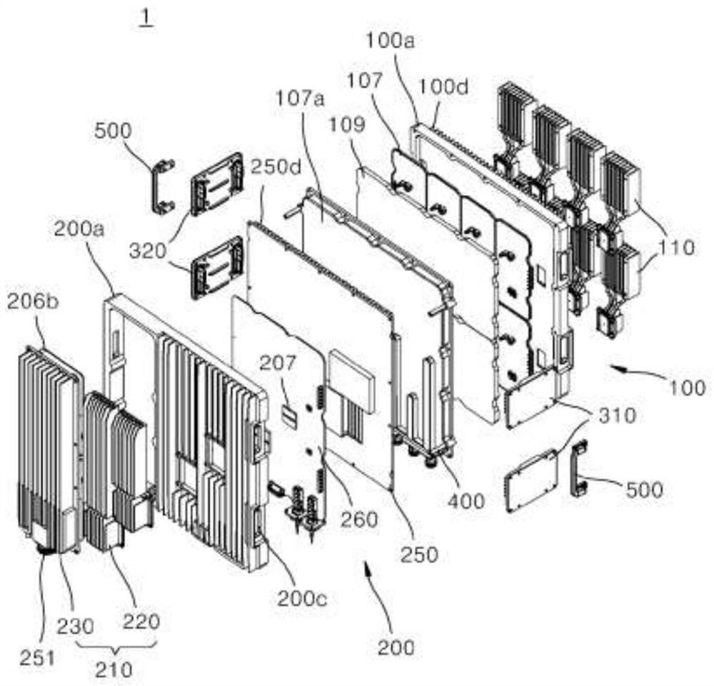
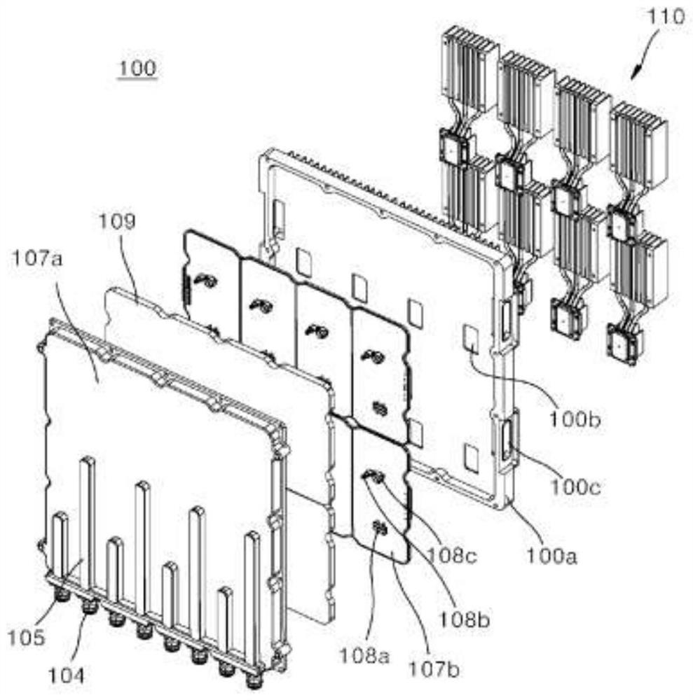
[0056] Hereinafter, an embodiment of the antenna device of the present invention will be described in detail with reference to the drawings. In attaching reference numerals to constituent elements in each drawing, care should be taken to assign the same reference numerals to the same constituent elements as much as possible even if they appear in different drawings. Also, in describing the embodiments of the present invention, when it is judged that a specific description of a related known structure or function hinders the understanding of the embodiments of the present invention, the detailed description thereof will be omitted.

[0057] In describing the structural elements of the embodiments of the present invention, the terms first, second, A, B, (a), (b), etc. may be used. Such terms are used to distinguish two structural elements, and the nature, sequence, or order of the corresponding structural elements are not limited to the above terms. And, as long as there is no ...


PUM


Abstract

The present invention relates to an antenna apparatus, which specifically comprises: a filter unit which is disposed to form at least one layer; an electric appliance unit which is coupled and is spaced apart from the filter unit to form a layer different from that of the filter unit, and includes various electric devices installed therein; a filter unit heat dissipation module which is coupled to the opposite surface of a surface of the filter unit, the surface being coupled to the electric appliance unit, and thus radiates heat generated from the filter unit to the outside; and an electric appliance unit heat dissipation module including a first electric appliance unit heat dissipation module and a second electric appliance unit heat dissipation module, wherein: the first electric appliance unit heat dissipation module is coupled to the opposite surface of a surface of the electric appliance unit, the surface being coupled to the filter unit, and thus radiates, to the outside, heat generated from first heating elements intensively disposed at one side of the filter unit; and the second electric appliance unit heat dissipation module is provided in parallel to the first electric appliance unit heat dissipation module and radiates, to the outside, heat generated from second heating elements intensively disposed at the other side of the filter unit. Accordingly, assembling performance is improved and heat dissipation performance is maximized.

Description

technical field [0001] The present invention relates to an antenna device (ANTENNA APPARATUS), and more specifically, to an antenna device for wireless communication. Background technique [0002] Wireless communication technology, for example, Multiple Input Multiple Output (MIMO, Multiple Input Multiple Output) technology is a technology that uses multiple antennas to greatly increase data transmission capacity. The Spatial multiplexing technology that distinguishes the transmitted data through appropriate signal processing in the device. [0003] Therefore, as the number of transmit and receive antennas increases simultaneously, the channel capacity will also increase, allowing more data to be transmitted. For example, if the number of antennas is increased to 10, compared with the current single-antenna system, about 10 times the channel capacity can be secured using the same frequency band. [0004] In 4G LTE-advanced, 8 antennas are used, and in the current pre-5G st...

Claims


Application Information

Patent Timeline
Patent Type & Authority Applications(China)
IPC IPC(8): H01Q1/02H01Q1/22H03H7/01
CPCH01Q1/246H01Q1/02H01Q1/22H03H7/0161H04B1/0078H04B1/036H04B1/04H04B2001/0408
Inventor 俞昌佑朴敏植
Owner KMW INC
Why Eureka
Try Eureka