
Detachable feeding and chopping device and harvester thereof

A shredding device and feeding device technology, which is applied in the field of harvesters, can solve the problems of increasing the difficulty of installation and disassembly, the inability to apply clamping force on corn stalks, and increasing the difficulty and cost of maintenance, so as to increase the connection stability, Reduce maintenance difficulty and cost, and facilitate disassembly

Pending Publication Date: 2021-09-07
河北英虎农业机械股份有限公司
View PDF9 Cites 0 Cited by
  • Summary
  • Abstract
  • Description
  • Claims
  • Application Information

AI Technical Summary

Problems solved by technology

The feeding part and the crushing part are composed of the same shell. On the one hand, it increases the difficulty of installation and disassembly. On the other hand, when the feeding part or the chopping part is damaged, it needs to be disassembled and installed as a whole, which increases the Difficulty and cost of maintenance
For example, the existing patent ZL201620119988.8 discloses a hay cutter with a corn grain crushing device on the forage harvester. The position of the fixed knife is fixed, so the cutting distance between the fixed knife and the moving knife cannot be adjusted, resulting in The gap (cutting length) between the moving blade and the moving blade is fixed and cannot be adjusted, and the length of the straw does not meet the requirements, reducing the quality of the silage
For example, the existing patent ZL201620045530.2 provides a fully floating feeding and chopping device and harvester for corn stalks. In addition, the bottom of the corn stalk is directly in frictional contact with the bottom of the shell, so that the feeding roller cannot quickly move the corn stalk to the crusher, which reduces the efficiency of straw crushing

Method used


Image

  • Detachable feeding and chopping device and harvester thereof
  • Detachable feeding and chopping device and harvester thereof
  • Detachable feeding and chopping device and harvester thereof

Examples


Embodiment Construction

[0035] Exemplary embodiments of the present disclosure will be described in more detail below with reference to the accompanying drawings. Although exemplary embodiments of the present disclosure are shown in the drawings, it should be understood that the present disclosure may be embodied in various forms and should not be limited to the embodiments set forth herein. Rather, these embodiments are provided so that the present disclosure can be more thoroughly understood and the scope of the present disclosure can be fully conveyed to those skilled in the art.

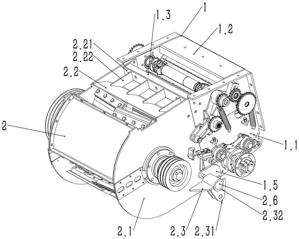
[0036] Such as figure 1 As shown, according to the embodiment of the present invention, a harvester is proposed, including a detachable feeding and chopping device, the feeding and chopping device is installed on the front end of the frame, and the front end of the feeding and chopping device is installed with Straw header.

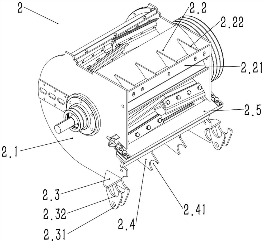
[0037] Such as figure 1 As shown, the feeding and chopping device includes a feeding device ...


PUM


Abstract

The invention discloses a detachable feeding and chopping device and a harvester thereof. The detachable feeding and chopping device comprises a feeding device and a chopping device, the feeding device is detachably installed on the chopping device and comprises a left feeding side plate, a right feeding side plate and a feeding middle plate connected with the two feeding side plates, and a feeding installation plate is further arranged between the two feeding side plates; the chopping device comprises a left chopping side plate, a right chopping side plate and a chopping middle plate connected with the two chopping side plates, a chopping installation plate is arranged at the front end of the chopping middle plate, the feeding installation plate and the chopping installation plate are connected together through a connecting part, and then the feeding device is detachably installed on the chopping device. The feeding device and the chopping device are detachably connected, the maintenance and installation difficulty and cost are reduced, fixed blades can be adjusted, the ensilage quality is improved, the feeding device comprises an upper-layer feeding roller and a lower-layer feeding roller, the upper-layer feeding roller clamps downwards, the grabbing force on corn stalks is improved, and the feeding and chopping device and the harvester thereof are convenient to maintain and install, high in ensilage quality and high in feeding and crushing efficiency.

Description

technical field [0001] The invention relates to a detachable feeding and chopping device and a harvester thereof, in particular to a feeding device and a harvester in which a feeding device and a chopping device are detachably connected, and belongs to the technical field of harvesters. Background technique [0002] The header device of the corn harvester generally includes an upper and lower header, a feeding device and a hay cutter (shredding device). The feeding device is used to transport the corn stalks cut by the lower header to the hay cutter for crushing. The feeding efficiency of the feeding device directly affects the efficiency of corn stalk harvesting and crushing. The feeding device is fixedly welded or combined with the hay cutter by means of the same side plate, and the two cannot be disassembled. In addition, the position of the fixed blade of the chopping device is fixed and cannot be adjusted. [0003] For example, the existing patent ZL201620045156.6 dis...

Claims


Application Information

Patent Timeline
IPC IPC(8): A01D45/02A01D43/08A01D75/00
CPCA01D45/02A01D43/08A01D75/00
Inventor 李衡李侠杨香林
Owner 河北英虎农业机械股份有限公司
Learn More