Equipment for automatically assembling and disassembling spinning components

A spinning assembly, automatic loading and unloading technology, applied in metal processing equipment, metal processing, manufacturing tools, etc., can solve the problems of low labor efficiency, complicated operation, and low efficiency

Pending Publication Date: 2021-09-07
WUJIANG LANGKE CHEM FIBER
View PDF7 Cites 0 Cited by
  • Summary
  • Abstract
  • Description
  • Claims
  • Application Information

AI Technical Summary

Problems solved by technology

The advantage of this method is that it does not require manual lifting, which reduces the labor intensity, but only one spinning assembly can be replaced each time, and it is necessary to manually drag a lifting tool weighing 1000KG to move on the truss, which is complicated, labor-intensive and time-consuming. Compared with manual labor, the efficiency is lower, the alignment accuracy is poor, manual tightening is not labor-saving, and workers are less willing to use this tool
[0006] In summary, it can be seen that no matter which of the above-mentioned component replacement methods is completely based on manual alignment and tightening, only one spinning component can be replaced at a time, which is inefficient; and the replacement method with the help of auxiliary tools is more effective than manual replacement. It is more complicated and less efficient, and the spinning assembly still needs to be manually tightened, which only saves the force of lifting the spinning assembly upwards, and does not change the working environment of the workers; therefore, it is urgent for those skilled in the art to change the status quo of the industry

Method used


Image

  • Equipment for automatically assembling and disassembling spinning components
  • Equipment for automatically assembling and disassembling spinning components
  • Equipment for automatically assembling and disassembling spinning components

Examples


Embodiment Construction

[0041] The present invention will be further described below in conjunction with the accompanying drawings and specific embodiments, so that those skilled in the art can better understand the present invention and implement it, but the examples given are not intended to limit the present invention.

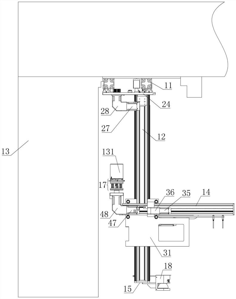
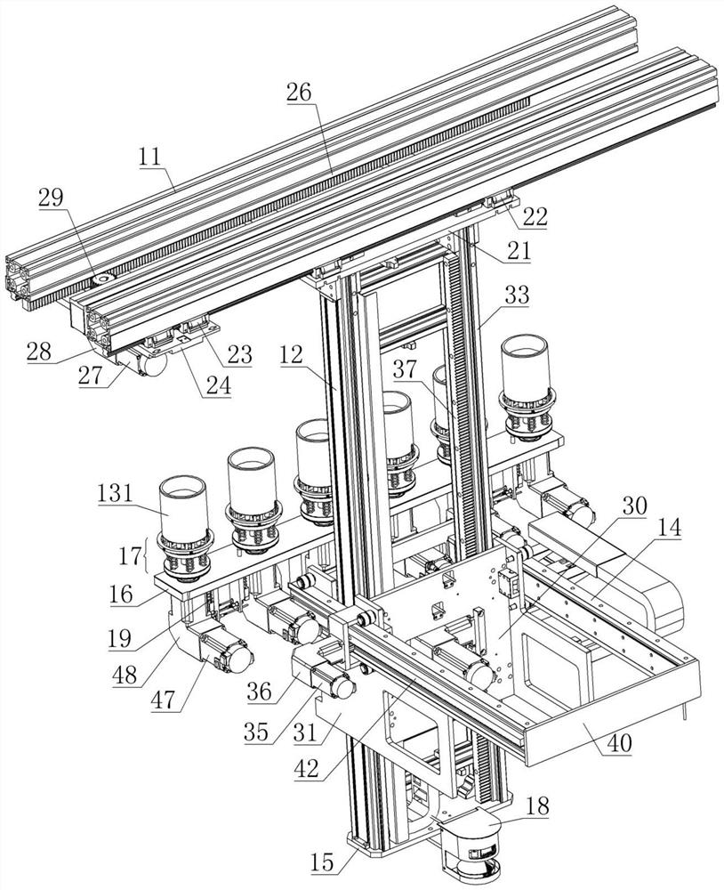
[0042] refer to Figure 1-Figure 2 As shown, an embodiment of a device for automatically loading and unloading the spinning assembly 131 of the present invention;

[0043] A device for automatically loading and unloading spinning assembly 131, comprising:

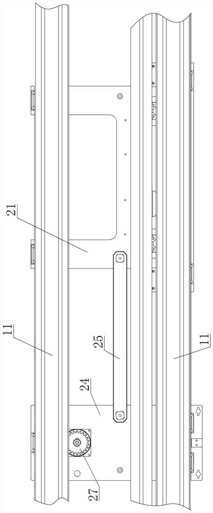
[0044] X-axis beam 11, the X-axis beam 11 is connected to the spinning beam 13;

[0045] The Z-axis longitudinal beam 12, one end of the Z-axis longitudinal beam 12 is slidably connected to the X-axis beam 11, and the Z-axis longitudinal beam 12 is connected with a first power to drive it to slide along the length direction of the X-axis beam 11 mechanism;

[0046] The Y-axis beam 14, the Y-axis beam 14 is slidably installed...


PUM


Abstract

The invention discloses equipment for automatically assembling and disassembling spinning components. The equipment comprises an X-axis cross beam, a Z-axis longitudinal beam and a Y-axis cross beam, wherein the X-axis cross beam, the Z-axis longitudinal beam and the Y-axis cross beam are combined to form a space coordinate system and are respectively driven by a power mechanism; the X-axis cross beam is connected onto a spinning manifold; a plurality of tightening components driven by the power mechanism to rotate are installed at the end part of the Y-axis cross beam; the X-axis cross beam, the Z-axis longitudinal beam and the Y-axis cross beam are combined to drive the tightening components to move in space; the tightening components drive the spinning components installed at the upper end of the tightening components to be aligned with corresponding component mounting holes in the spinning manifold; the power mechanism drives the tightening components to rotate so as to drive the spinning components to rotate; and the rotating spinning components are screwed on the corresponding component mounting holes through threads. The assembly and disassembly process of the spinning components does not need to be directly operated manually, the labor intensity of workers is reduced, manpower is saved, multiple spinning components can be disassembled and assembled at the same time, the component replacement efficiency is high, and the production efficiency can be effectively improved.

Description

technical field [0001] The invention relates to the technical field of loading and unloading equipment for spinning components, in particular to a device for automatically loading and unloading spinning components. Background technique [0002] Usually in spinning production, when the melt pressure in the spinning box is close to or exceeds the set value, if it continues to run, it will affect the safety of the spinning box and cause melt leakage. The main reason for this phenomenon is It is caused by the filter screen in the spinning assembly being polluted in a large area, or a large number of spinneret holes are blocked. Therefore, the spinning assembly needs to be replaced in time. [0003] In the prior art, there are two main ways to replace the spinning assembly: [0004] The first method is manual replacement. When installing the spinning assembly, one person uses a special fork to place the spinning assembly on the tightening wrench, and the other lifts the wrench w...

Claims


Application Information

Patent Timeline
IPC IPC(8): B23P19/06B23P19/10
CPCB23P19/06B23P19/10
Inventor 卢思源卢贤生葛炜许华强
Owner WUJIANG LANGKE CHEM FIBER
Why Eureka
Try Eureka