A prepreg tape automatic laying device

A prepreg tape, laying technology, applied in the direction of final product manufacturing, manufacturing tools, laser welding equipment, etc., can solve the problems of low laying efficiency, adhesion and pulling on the surface of the anvil knife and the tape, and can only be layered layer by layer. , to achieve the effect of ensuring the laying effect, saving laying time and improving production efficiency

Active Publication Date: 2022-07-08
CHANGSHA UNIVERSITY OF SCIENCE AND TECHNOLOGY
View PDF0 Cites 0 Cited by
  • Summary
  • Abstract
  • Description
  • Claims
  • Application Information

AI Technical Summary

Problems solved by technology

[0005] 1. The automatic laying technology of the prior art is to lay the prepreg tape layer by layer on the surface of the mold. After laying several layers, the composite material component reaches a certain thickness. Therefore, for laying multi-layer prepreg tape The mold can only be stacked layer by layer, and the laying efficiency is low
[0006] 2. At the end of laying each path, the laying mechanism must go back and forth or turn around to re-lay the previous laying path or lay the next path. Therefore, during the automatic laying process, the laying mechanism needs to Multiple round trips or U-turn laying, wasting a lot of time
[0007] 3. The existing cutting method is the contact cutting of the cutting board and the anvil knife. Since the strip material is moving during the laying process, the contact cutting is easy to cause adhesion and pulling of the anvil knife and the surface of the strip material, which will cause unnecessary damage to the strip material. The tension will affect the laying effect of the tape at the moment of cutting

Method used


Image

  • A prepreg tape automatic laying device
  • A prepreg tape automatic laying device
  • A prepreg tape automatic laying device

Examples


Embodiment Construction

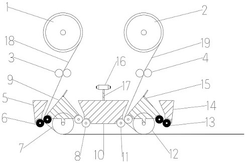
[0031] As shown in the figure: an automatic prepreg tape laying device, including a feeding mechanism, a laying mechanism, a cutting mechanism, a guiding mechanism and a reversing mechanism, and the cutting mechanism is arranged in the horizontal direction. Between the reversing mechanisms, the reversing mechanism is located directly below the feeding mechanism, wherein:

[0032] The feeding mechanism includes a left tape roll 1, a right tape roll 2, a first pair of nip rolls 3, a second pair of nip rolls 4, a first prepreg tape 18 and a second prepreg tape 19. The first The prepreg tape 18 is sleeved on the left tape roll 1 , the first pair of clamping rollers 3 are two clamping rollers arranged symmetrically on the left and right, and the first pair of clamping rollers 3 are located on the left tape roll 1 . Below, the second prepreg tape 19 is sleeved on the right tape roll 2, the second pair of clamping rollers 4 are two clamping rollers arranged symmetrically on the left ...


PUM


Abstract

An automatic prepreg tape laying device, comprising a feeding mechanism, a laying mechanism, a cutting mechanism, a guiding mechanism and a reversing mechanism, the feeding mechanism comprises a left tape roll, a right tape roll, a first pair of clamping rollers, a Two pairs of nip rollers, a first prepreg tape and a second prepreg tape, the laying mechanism includes a first pair of heating rolls, a first pressing roll, a first pair of rolls for laying, a second pair of rolls for laying, a second pair of rolls for laying Two pressing rollers and a second pair of heating rollers, the guiding mechanism includes a first guiding mechanism, a third guiding mechanism and a second guiding mechanism, the cutting mechanism includes a double-head laser cutter and a support frame, the The reversing mechanism includes a first reversing mechanism and a second reversing mechanism. The prepreg tape automatic laying device does not need to be laid layer by layer at a time, which greatly improves the production efficiency, and at the same time, it does not need to return or turn around in an empty way, which saves the laying time.

Description

technical field [0001] The invention relates to the field of automatic laying, in particular to an automatic laying device for prepreg tapes. Background technique [0002] The automatic laying technology has the characteristics of high efficiency, high quality, high reliability and low cost, and is especially suitable for the manufacture of large-sized components, reducing the number of assembled parts, saving manufacturing and assembly costs, and greatly reducing the waste rate of materials It is widely used in the manufacture of aerospace high-performance composite structures. [0003] The automatic laying technology uses the prepreg tape as the raw material. After heating, it is directly laid on the surface of the mold or the upper layer of the prepreg tape under the action of the pressing roller to realize the automatic forming of the composite material laying. [0004] Disadvantages of the prior art: [0005] 1. The automatic laying technology of the prior art is to l...

Claims


Application Information

Patent Timeline
Patent Type & Authority Patents(China)
IPC IPC(8): B29C70/34B29C70/38B29C70/54B23K26/38
CPCB29C70/34B29C70/386B29C70/545B23K26/38Y02P70/50
Inventor 张鹏冯文明缑建杰胡波尹来容邓连辉
Owner CHANGSHA UNIVERSITY OF SCIENCE AND TECHNOLOGY
Why Eureka
Try Eureka