Eddy current displacement sensor and method for expanding linear range of eddy current displacement sensor
A technology of displacement sensor and linear range, which is applied in the direction of instruments, electric devices, and electromagnetic means, etc. It can solve the problems of short detection distance, low sensitivity at the far end, narrow linear area, etc., and achieve the effect of a large degree of linearization
- Summary
- Abstract
- Description
- Claims
- Application Information
AI Technical Summary
Problems solved by technology
Method used
Image
Examples
Embodiment 1
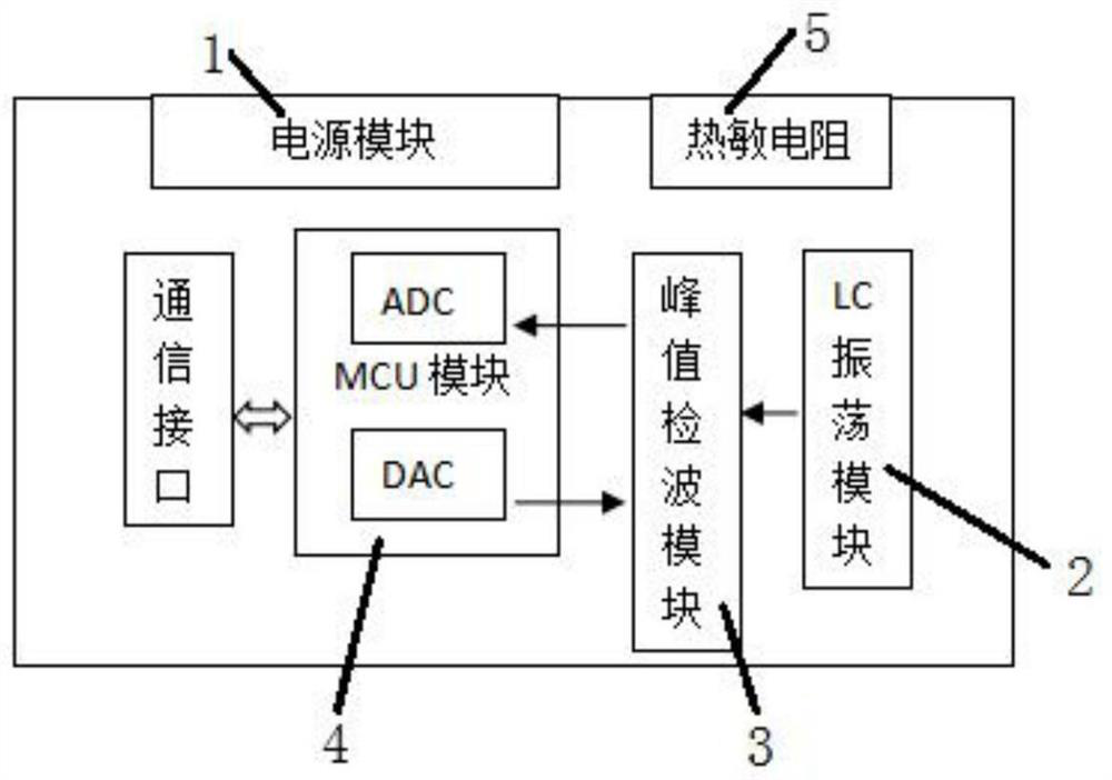
[0045] An eddy current displacement sensor, the eddy current displacement sensor includes a power supply module 1, an LC oscillation module 2, an MCU module 4 and a peak detection module 3, wherein,
[0046] The LC oscillation module 2 includes a coil ferrite and a positive feedback pulse comparison circuit. The LC oscillation module 2 provides a stable sinusoidal signal, wherein the positive feedback pulse comparison circuit is a stable oscillation circuit, which mainly provides a sinusoidal signal. The above LC oscillation module 2 is a high-precision low-temperature drift resistance container device. The temperature of the oscillation circuit is mainly determined by the temperature characteristics of the device itself. Here, a high-precision low-temperature drift resistance container device is selected. The key coils are closely arranged and wound with multi-strand enameled wires. Mounted in low temperature drift ferrite with magnetic permeability. In addition, the coil is ...
Embodiment 2
[0052] A method for expanding the linear range of an eddy current displacement sensor, comprising the following steps:
[0053] (1) Place the eddy current displacement sensor at a certain distance from the object to be measured, and the LC oscillation module 2 of the eddy current displacement sensor sends out an oscillation signal (sinusoidal signal);
[0054] (2) the MCU module 4 of the eddy current displacement sensor collects and outputs the DAC output voltage;
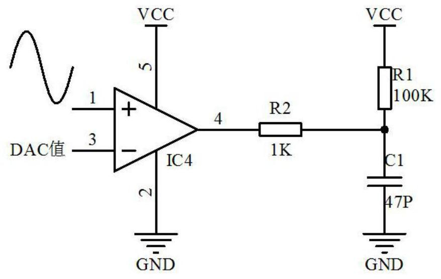
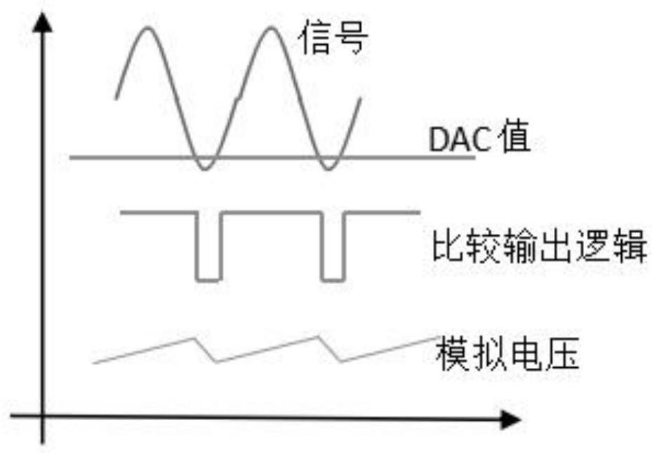
[0055] (3) The peak detection module 3 converts the oscillating signal (sinusoidal signal) into an analog quantity change, such as figure 2 and image 3 As shown, the comparator opens the drain output, the trough of the oscillation signal is compared with the DAC value, the object under test is close to the sensor, the oscillation signal (sinusoidal signal) decays and tends to stop the oscillation, and the comparison output logic ( figure 2 The output state of the output pin 4 of IC4) the low pulse width decrea...
PUM
 Abstract
Description
Claims
Application Information
 - R&D
- Intellectual Property
- Life Sciences
- Materials
- Tech Scout
- Unparalleled Data Quality
- Higher Quality Content
- 60% Fewer Hallucinations
Browse by: Latest US Patents, China's latest patents, Technical Efficacy Thesaurus, Application Domain, Technology Topic, Popular Technical Reports.
© 2025 PatSnap. All rights reserved.Legal|Privacy policy|Modern Slavery Act Transparency Statement|Sitemap|About US| Contact US: help@patsnap.com


