
Noise testing method and device

A noise test and noise technology, applied in the field of noise test methods and devices, can solve the problems of wasting manpower and material resources, prolonging the product development cycle, and uncertain relations, etc., to reduce development costs, shorten product development cycles, and save manpower and material resources Effect

Pending Publication Date: 2021-09-07
江苏徐工国重实验室科技有限公司
View PDF0 Cites 0 Cited by
  • Summary
  • Abstract
  • Description
  • Claims
  • Application Information

AI Technical Summary

Problems solved by technology

[0004] The inventor found that there are at least the following problems in the related technology: the related technology cannot determine the relationship between the noise of each component and the passing noise, lacks a calculation and prediction method for the noise of the whole machine, cannot obtain the noise distribution, and cannot effectively know the direction of the noise It is impossible to put forward the noise control requirements of parts and components, and it is impossible to control the noise of the whole machine from the design stage. It often takes several rounds of rectification after the prototype is offline to make the noise meet the requirements, which not only prolongs the product development cycle, but also wastes manpower. material resources, increasing product development costs
If commercial acoustic simulation software is used for vehicle-level noise simulation, since there are many noise sources and the frequency characteristics of different noise sources are different, it is necessary to comprehensively use simulation methods such as finite element method and statistical energy method, and the modeling and calculation will take a long time, and Simulation needs to obtain many parameters, and some parameters are difficult to obtain
Therefore, the vehicle-level noise simulation has not been applied in the construction machinery industry

Method used


Image

  • Noise testing method and device
  • Noise testing method and device
  • Noise testing method and device

Examples


Embodiment Construction

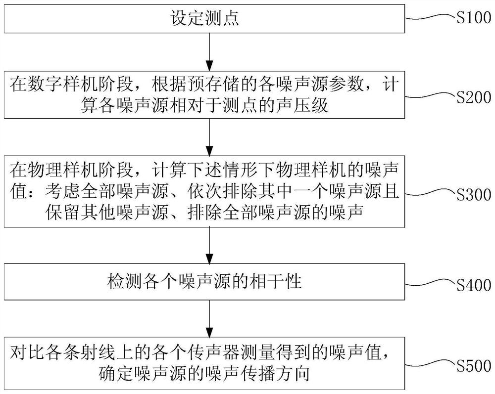
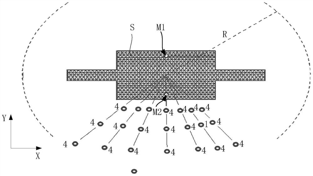
[0075] Combine below Figure 1 to Figure 7 The technical solution provided by the present invention is described in more detail.

[0076] During the research and development of construction vehicles, the noise of the designed products needs to meet the relevant construction machinery noise limit requirements.

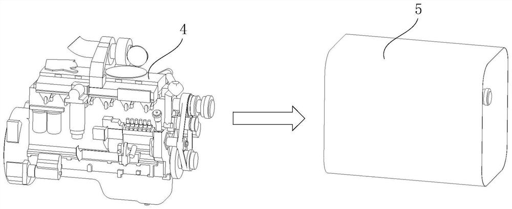
[0077] The noise sources of engineering vehicles mainly include engine 1, fan 3, and intake and exhaust components 2. The power of the engine 1 is large, so the noise is high. The fan 3 is used for cooling, and has a large diameter and a high rotating speed, so it is also noisy. The noise generated by the intake and exhaust assembly 2 during the intake and exhaust processes cannot be ignored. These factors together lead to the large radiation noise of the whole machine. The noise testing method provided by the embodiment of the present invention can predict the noise situation of each main noise source of the vehicle in the state of the whole vehicle, so as to provi...


PUM


Abstract

The invention discloses a noise testing method and device and relates to the field of engineering machinery, and the method and the device are used for predicting the noise of a whole vehicle. The noise testing method comprises the following steps: setting a test point; in the digital prototype stage, calculating the sound pressure level of each noise source relative to the measuring point according to the pre-stored parameters of each noise source; and in the physical prototype stage, calculating the noise value of a physical prototype under the following conditions: all noise sources are considered, one of the noise sources is eliminated in sequence, other noise sources are reserved, and the noise of all the noise sources is eliminated. According to the noise test method provided by the technical scheme, the noise can be measured in a whole vehicle mode in both the digital prototype stage and the physical prototype stage, and the test results of the digital prototype stage and the physical prototype stage are mutually coupled, so that an effective mode is provided for the overall noise prediction of the vehicle.

Description

technical field [0001] The invention relates to the field of engineering machinery, in particular to a noise testing method and device. Background technique [0002] Engineering vehicles have high engine power and high noise, and the cooling fan has a large diameter, high speed, and high noise, resulting in high radiation noise from the whole machine, causing environmental noise pollution, and seriously affecting human physical and mental safety. Therefore, countries and regions such as China and the European Union have issued strict noise limit requirements for construction machinery to control the noise pollution of construction machinery products. For example, China's "GB1495-2002 Vehicle Acceleration Exterior Noise Limits and Measurement Methods", this standard sets the mandatory requirements for the passing noise of construction vehicles, and requires that the product noise cannot meet the standard requirements. If the noise of the product exceeds the standard, the cer...

Claims


Application Information

Patent Timeline
IPC IPC(8): G01H17/00
CPCG01H17/00
Inventor 苏俊收高磊磊刘汉光
Owner 江苏徐工国重实验室科技有限公司
Learn More