A Memristor-Based Complete Non-Volatile Boolean Logic Circuit and Method of Operation
A Boolean logic and logic circuit technology, applied in the field of microelectronic devices, can solve problems such as high Boolean logic operations, and achieve the effects of high number of devices and operation steps, realization of logic functions, and simple structure
- Summary
- Abstract
- Description
- Claims
- Application Information
AI Technical Summary
Problems solved by technology
Method used
Image

Examples
Embodiment 1
[0070] A memristor-based complete non-volatile Boolean logic circuit for performing logic operations on an input logic value P and / or an input logic value Q;
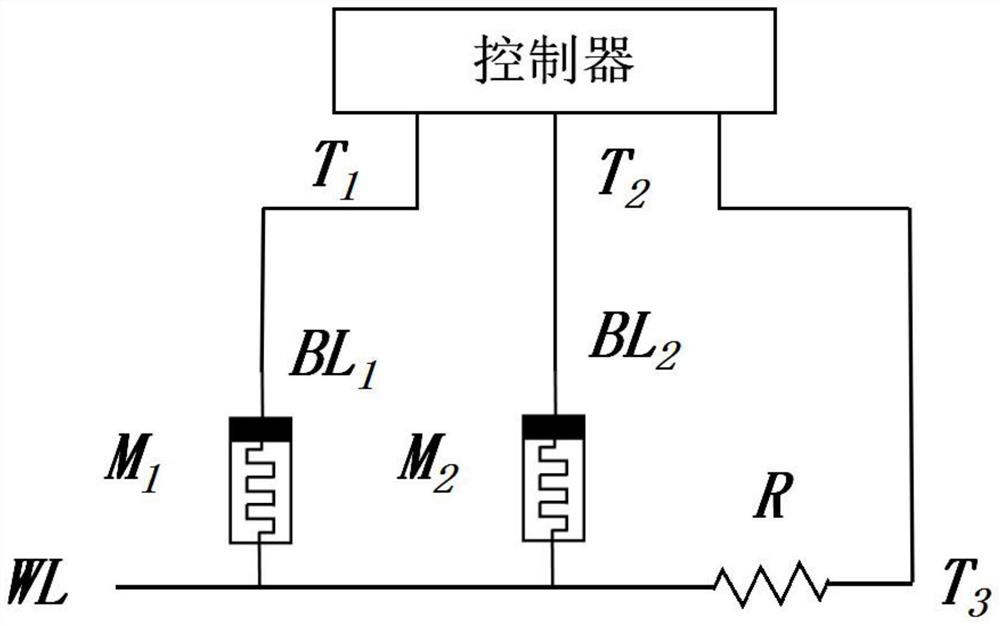
[0071] Such as figure 1 As shown, the above logic circuit includes: a controller, a memristor M 1 , memristor M 2 And resistance (this embodiment adopts fixed-value resistance);
[0072] The controller is connected with the memristor M 1 The positive electrode of the memristor M 2 The positive pole of the resistor is connected to one end of the resistor; the memristor M 1 and memristor M 2 The positive poles of the resistors are connected to different bit lines, and the negative poles are connected to the same word line WL; the other end of the resistor is connected to the word line WL; the memristor M 1 and memristor M 2 the same; specifically, the controller includes a control terminal T 1 , control terminal T 2 and the control terminal T 3 ;Control terminal T 1 via bit line BL 1 with memristor M 1 The po...
Embodiment 2
[0080] A method of operation based on the complete non-volatile Boolean logic circuit described in Embodiment 1, such as Figure 4 shown, including the following steps:
[0081] S1, the memristor M 2 Set to high impedance state;
[0082] S2. Determine whether the current operation is an operation related to the logic value Q, and if so, set the memristor M 1 Set to the resistance state corresponding to the logic value Q; wherein, the operation related to the logic value Q includes the operation of logical operation on the logic value P and the logic value Q and the operation of only performing the logic operation on the logic value Q;
[0083] S3, for the memristor M 1 Applied voltage A, on the memristor M 2 Apply voltage B, apply voltage C to the resistor, and read the memristor M 2 The resistance state is the result of logic operation;
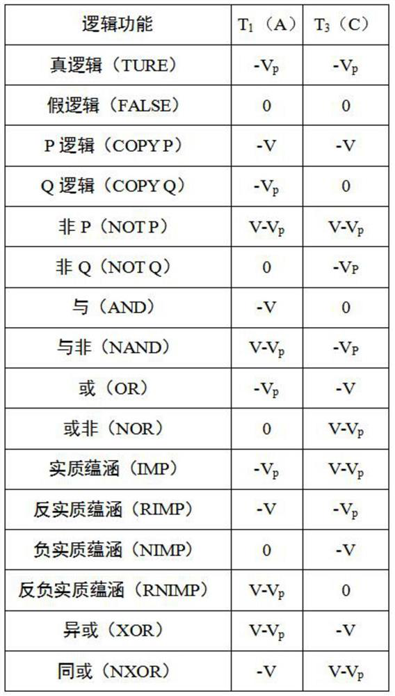
[0084] Among them, the value of voltage A and voltage C is determined by the logic value P and the type of logic operation; the value...
Embodiment 3
[0114] A logic cascading method based on the complete non-volatile Boolean logic circuit described in Embodiment 1, comprising:
[0115] Use the result of the previous logic operation obtained by the operation method described in Embodiment 2 as a new input logic value Q, and operate again according to the operation method described in Embodiment 2, thereby realizing logic cascading.
[0116] In this embodiment, the output of the logic operation in the previous step is stored in the memristor M in the form of a resistive state. 2 In this method, the result obtained by the logic calculation in the previous step is directly used as the input of the logic operation in the next step, that is, the memristor M which saves the calculation result in the previous step 2 Directly regarded as the input memristor M of the logic calculation of the next step 1 .
[0117] In summary, the present invention discloses a complete non-volatile Boolean logic circuit and operation method based on...
PUM
 Abstract
Description
Claims
Application Information
 - R&D
- Intellectual Property
- Life Sciences
- Materials
- Tech Scout
- Unparalleled Data Quality
- Higher Quality Content
- 60% Fewer Hallucinations
Browse by: Latest US Patents, China's latest patents, Technical Efficacy Thesaurus, Application Domain, Technology Topic, Popular Technical Reports.
© 2025 PatSnap. All rights reserved.Legal|Privacy policy|Modern Slavery Act Transparency Statement|Sitemap|About US| Contact US: help@patsnap.com