Positioning and pressing process method for horizontal lamination of stator main iron core

A process method and iron core technology, applied in the field of stator main iron core horizontal stacking positioning and compaction technology, can solve the problem of stator main core damage, horizontal lamination and compaction work is very difficult, and lamination and compaction cannot be solved and other issues to achieve the effect of saving procurement and manufacturing, shortening the repair period, and reducing repair costs

Active Publication Date: 2021-09-07
HARBIN ELECTRIC MASCH CO LTD
View PDF16 Cites 0 Cited by
  • Summary
  • Abstract
  • Description
  • Claims
  • Application Information

AI Technical Summary

Problems solved by technology

[0002] When the turbogenerator is running on site, sometimes the stator core is damaged due to various reasons. Generally, the stator side core at the end is damaged, but sometimes the main stator core is damaged.
[0003] When the stator main core is damaged and needs to be repaired on site, it cannot be repaired according to the method of erecting the stator in the manufactory for lamination and compaction, and the horizontal lamination and compaction work on site is very difficult
[0004] The stator main core punch is positioned against the positioning ribs on the back, but there is a certain gap between the punch and the positioning ribs. When the laminations are stacked vertically in the manufacturing plant, this gap can meet the positioning requirements without affecting the cylindricity of the stator main core. When there is a deviation, when the laminations are horizontally stacked on site, all the punches will be shifted downward due to their own weight, so that the inner diameter of the stator main core is qualified in the horizontal direction and the vertical direction is small, and there are many punches that need to be removed when the stator main core is repaired horizontally on site , to prevent the ellipse problem of the stator main core is difficult to deal with
[0005] There are many stampings that need to be re-stacked during the horizontal repair of the stator main core on site. These stampings will be looser in the horizontal lamination. Compared with the vertical lamination in the manufacturing plant, the self-weight of the stamping will make the stator The main iron core is relatively compact, and it is more difficult to compress the horizontal laminations of the stator main iron core on site

Method used


Image

  • Positioning and pressing process method for horizontal lamination of stator main iron core
  • Positioning and pressing process method for horizontal lamination of stator main iron core
  • Positioning and pressing process method for horizontal lamination of stator main iron core

Examples


Embodiment Construction

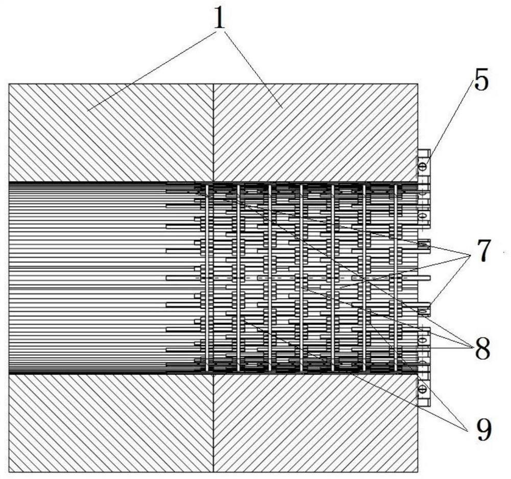
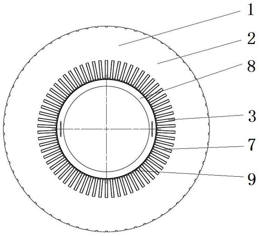
[0031] Horizontal stacking positioning and compacting process of the main iron core of the turbogenerator stator. Its technological implementation process is as follows:

[0032] 1) Remove the stamping plate 2 of the stator main core 1 of the damaged part on site;

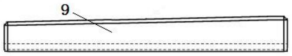
[0033] 2) Press figure 1 and figure 2 and image 3 As shown, a positioning support plate 7 is installed in the lower wire slot 3 of the stator main core 1, and a positioning support plate 7 is installed every two lower wire slots 3. The axial length of the positioning support plate 7 in the old stator main core 1 is 300mm. The length of the main stator core 1 protruding out is 200mm, and two support rings 8 are installed on the inner diameter of the old stator main core 1, one is located at the end of the positioning support plate 7, and the other is located in the middle of the positioning support plate 7, the positioning support plate 7 and the support ring 8 The small V-shaped wedges 9 with a taper are fast...


PUM


Abstract

The invention discloses a positioning and pressing process method for horizontal lamination of a stator main iron core, which is characterized in that a positioning tool is spirally mounted and used in a coil inserting slot of the stator main iron core in an overlapping manner, so that the cylindricity of the stator main iron core during horizontal lamination is ensured while positioning in the lamination process is completed; in the lamination process of the main iron core of the stator, a tool finger pressing sheet is used for assembling and pressing a cage frame and a small jack, so that a punching sheet is pressed tightly; and when the lamination of the stator main iron core is finished, the pressing work of the stator main iron core after the horizontal lamination of a large number of punching sheets is finished by using a tool to press finger sheet assembly, a simple pressing tool and a product pressing ring.

Description

technical field [0001] The invention relates to the on-site repair technology of the stator main iron core of a steam turbine generator, in particular to a horizontal stacking positioning and compaction process of the stator main iron core. Background technique [0002] When the turbogenerator is running in the field, sometimes the stator core is damaged due to various reasons. Generally, the stator side core at the end is damaged, but sometimes the main stator core is damaged. [0003] When the stator main core is damaged and needs to be repaired on site, it cannot be repaired according to the method of erecting the stator in the manufacturing plant for lamination and compaction. The horizontal lamination and compaction work on site is very difficult. [0004] The stator main core punch is positioned against the positioning ribs on the back, but there is a certain gap between the punch and the positioning ribs. When the laminations are stacked vertically in the manufacturin...

Claims


Application Information

Patent Timeline
Patent Type & Authority Applications(China)
IPC IPC(8): H02K15/00H02K15/02
CPCH02K15/0006H02K15/026Y02T10/64
Inventor 刘俊英温海明安华杨长泳刘继海孟秋宋宏超董巍王莉学王永春
Owner HARBIN ELECTRIC MASCH CO LTD
Why Eureka
Try Eureka