Separation apparatus and separation method

a separation apparatus and separation method technology, applied in the direction of band saws, manufacturing tools, saw chains, etc., can solve the problems of increasing and reducing the overall thickness of the portable electronic device. , to achieve the effect of reducing the rework or repair cos

Active Publication Date: 2010-05-06
HTC CORP
View PDF2 Cites 28 Cited by
  • Summary
  • Abstract
  • Description
  • Claims
  • Application Information

AI Technical Summary

Benefits of technology

[0012]In summary, the present application employs a cutting member to separate two planar devices that are bonded by an adhesive layer. Therefore, when one of the planar devices needs to be replaced, the present application can be used to separate the planar devices to keep the other one of the planar devices, thus reducing the rework or repair cost.

Problems solved by technology

The display module and touch panel of the portable electronic device conventionally are assembled to a housing of the portable electronic device separately, which may lead to a gap between the display module and the touch panel.
However, such a gap is disadvantageous in reducing an overall thickness of the portable electronic device.
However, when the touch panel needs to be replaced due to a failure or scratch, replacing the touch panel causes a replacement of the display module accordingly because the display module has been already bonded to the touch panel, thus increasing rework and repair cost.

Method used


Image

  • Separation apparatus and separation method
  • Separation apparatus and separation method
  • Separation apparatus and separation method

Examples


Embodiment Construction

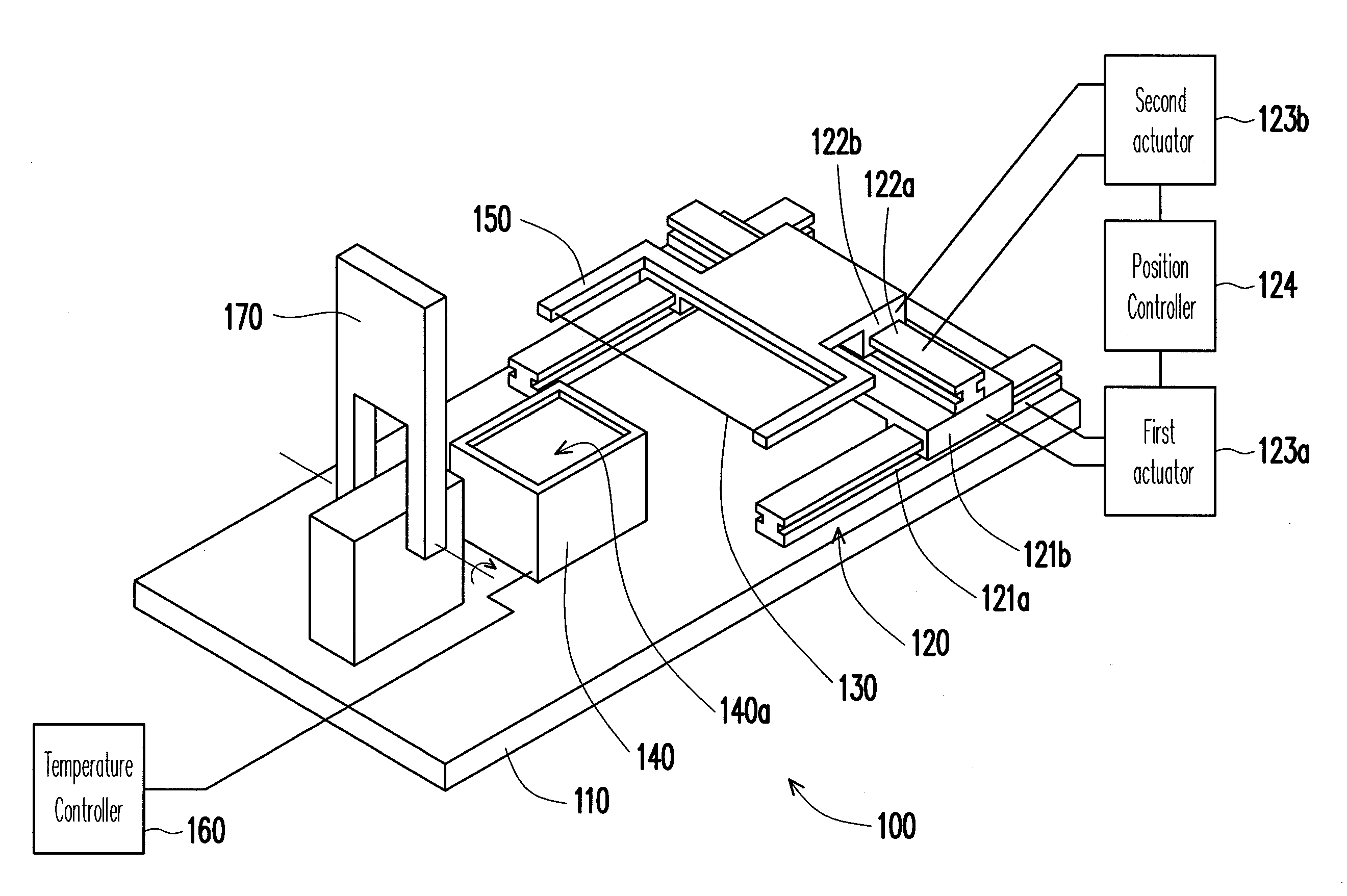
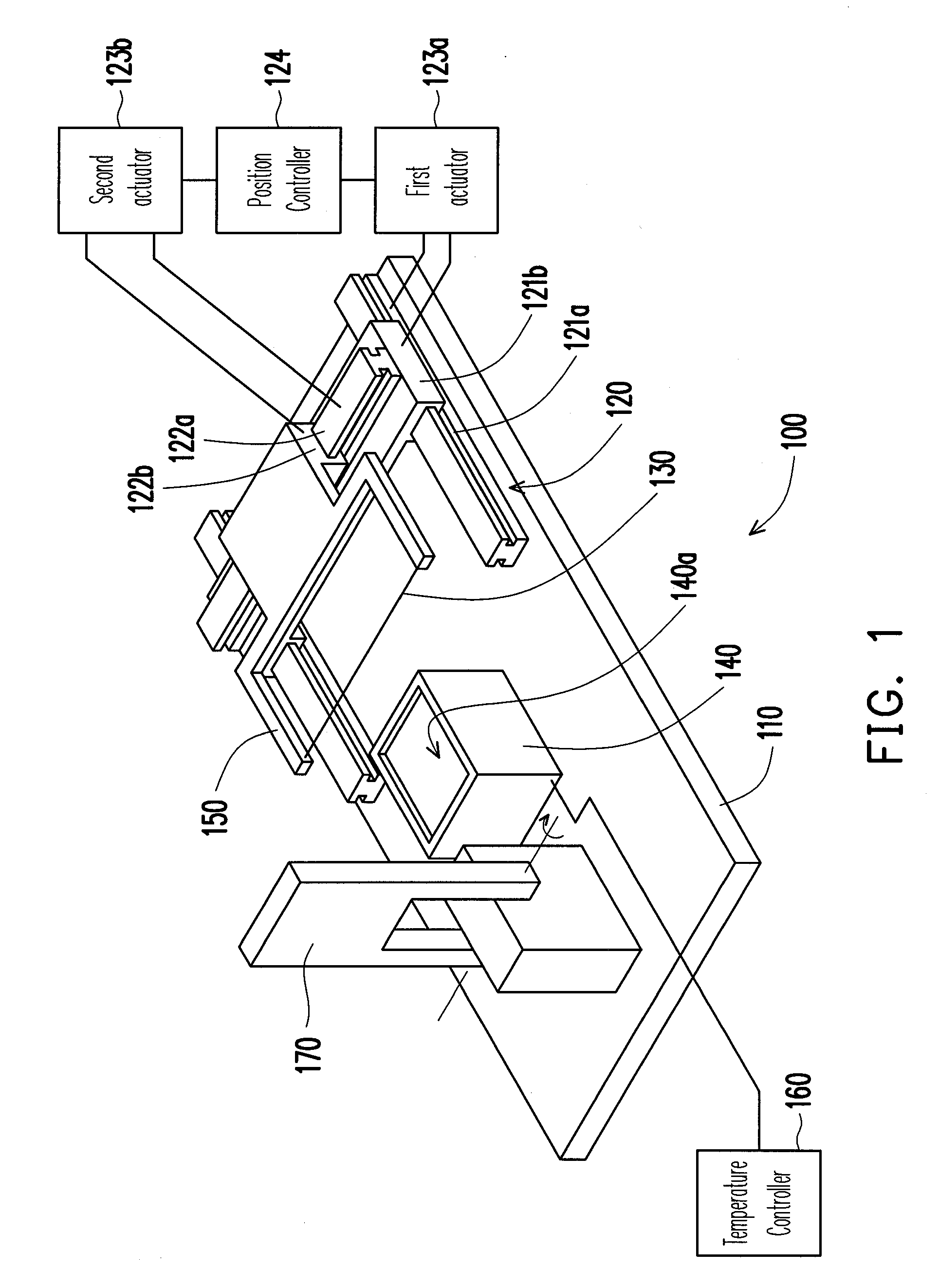
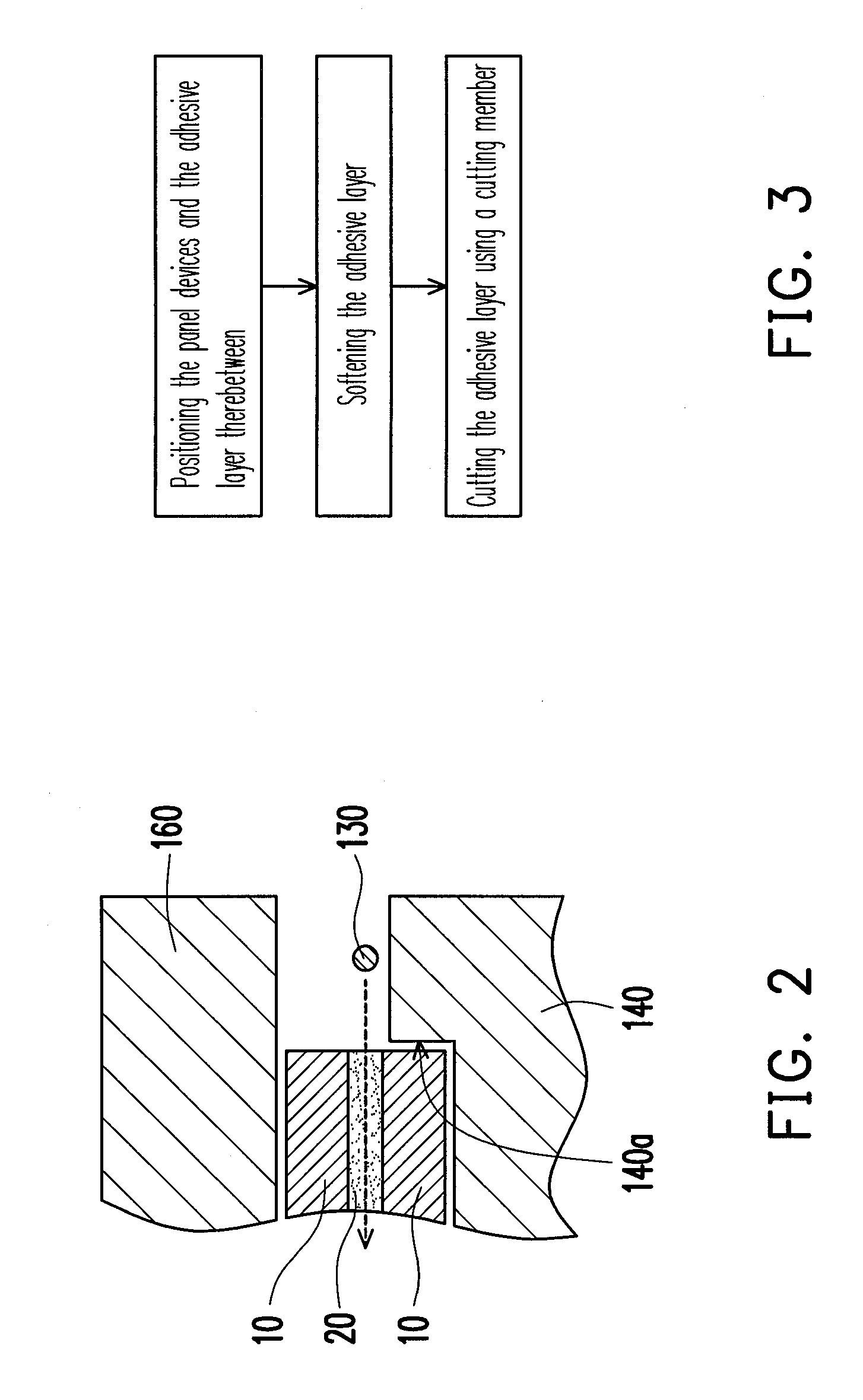
[0017]FIG. 1 is a perspective view of a separation apparatus according to one embodiment of the present invention, and FIG. 2 is a cross-sectional view of the separation apparatus of FIG. 1 wherein the separation apparatus is being used to separate two planar devices bonded by an adhesive layer. Referring to FIG. 1 and FIG. 2, the separation apparatus 100 of the present embodiment is suitable for separating two planar devices 10 that are bonded by an adhesive layer 200. In the present embodiment, the planar devices 10 are a display module and a touch panel, respectively. The display module may be a liquid crystal display module. The touch panel may be a resistive touch panel, a capacitive touch panel, an infrared touch panel, or other types of touch panels. However, in an alternative embodiment not illustrated, these planar devices 10 may be a display module and a protective sheet made of a plastic or glass material. In a further alternative embodiment not illustrated, these planar ...


PUM

PropertyMeasurementUnit
heating capabilityaaaaaaaaaa
temperatureaaaaaaaaaa
sizeaaaaaaaaaa

Abstract

A separation apparatus for separating two planar devices bonded together by an adhesive layer is provided. The separation apparatus includes a base, a sliding module, a cutting member, and a positioning stage. The sliding module is mounted on the base. The cutting member is connected to the sliding module and is moveable in a two-dimensional plane with respect to the base by the sliding module for cutting the adhesive layer. The positioning stage is mounted on the base for positioning the planar devices and the adhesive layer therebetween on the base.

Description

CROSS-REFERENCE TO RELATED APPLICATION[0001]This application claims the priority benefit of Taiwan application serial no. 97142574, filed on Nov. 4, 2008. The entirety of the above-mentioned patent application is hereby incorporated by reference herein and made a part of specification.BACKGROUND OF THE INVENTION[0002]1. Field of the Invention[0003]The present application generally relates to a separation apparatus and a separation method, and more particularly, to a separation apparatus and a separation method for separating two planar devices that are bonded together by an adhesive layer.[0004]2. Description of Related Art[0005]Portable electronic devices usually are equipped with a display module to display images to users. The display module of some portable electronic devices is further provided with a touch panel in replace of a physical keyboard such that the portable electronic device can still provide a larger image size in its limited primary vision area.[0006]The display m...

Claims


Application Information

Patent Timeline
Patent Type & Authority Applications(United States)
IPC IPC(8): B26D7/10B26D5/08
CPCB23D49/02B23D57/0007B26D1/547B26D3/28B26D5/08B26D7/10Y10S156/924Y10T83/9292Y10T83/041Y10T83/8726Y10T83/75Y10T83/4722Y10T83/7507Y10T83/8887Y10T83/472Y10T83/937Y10T83/283Y10T83/8853Y10T156/1967Y10T156/1961Y10T156/11
Inventor LAI, YAO-HSIANGLIU, TA-CHENGHUNG, JUNG-HUNGLIN, YU-MENGYANG, KUO-LUNG
Owner HTC CORP
Why Eureka
Try Eureka