Indoor convenient fire fighting device

A fire-fighting device and convenient technology, applied in fire rescue and other directions, can solve problems such as difficulty in achieving efficient fire-fighting, intertwining, folding, and unfavorable fire-fighting operations.

Inactive Publication Date: 2021-09-10
王竹青
View PDF0 Cites 2 Cited by
  • Summary
  • Abstract
  • Description
  • Claims
  • Application Information

AI Technical Summary

Problems solved by technology

[0003] However, in the traditional fire box and other equipment, in order to ensure that the water output of the water gun is sufficient and efficient when a fire needs to be extinguished, it is usually necessary to lay the hose flat to avoid bending, twisting and knotting of the hose, and then put the water The valve can only be opened after the hose, the water gun and the water outlet are connected. The operation is too troublesome, and when some fires are close to the fire box, the entire hose needs to be opened and arranged before the water can flow, which leads to a serious waste of time. Not only is it a waste of time to open the hose, but the water in the hose needs to pass through the entire hose to be ejected from the water gun, which is even more time-consuming. Moreover, due to the short distance, it is easy for the hoses to entangle and fold after they are separated. , if there are folds between the hoses, it will also reduce the water output of the hoses. In this way, the best rescue time may be missed, and it is difficult to achieve efficient fire fighting; Tighten the hose connector of the hose so that the fire hose is screwed into the fire hydrant, and then the valve of the fire hydrant is opened to extinguish the fire with water. This process is complicated and takes a certain amount of time. Seconds represent life and economic losses, this setting is not conducive to the first time to start fire fighting operations

Method used


Image

  • Indoor convenient fire fighting device
  • Indoor convenient fire fighting device
  • Indoor convenient fire fighting device

Examples


Embodiment Construction

[0022] The following will clearly and completely describe the technical solutions in the embodiments of the present invention with reference to the accompanying drawings in the embodiments of the present invention. Obviously, the described embodiments are only some, not all, embodiments of the present invention. Based on the embodiments of the present invention, all other embodiments obtained by persons of ordinary skill in the art without making creative efforts belong to the protection scope of the present invention.

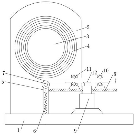
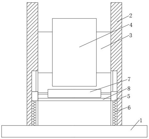
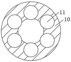
[0023] see Figure 1-6 , a convenient fire-fighting device for indoor use, comprising a base 1, side plates 2 are fixedly connected to both sides of the upper end of the base 1, the middle parts of the two side plates 2 are movably sleeved with a take-up pulley 3, and the middle part of the take-up pulley 3 is movable The hose 4 is socketed, the bottom of the inner side of the side plate 2 is movably socketed with a slider 5, the bottom of the slider 5 is fixe...


PUM


Abstract

The invention relates to the technical field of fire fighting equipment, and discloses an indoor convenient fire fighting device which comprises a base. Side plates are fixedly connected to the two sides of the upper end of the base, the middles of the two side plates are movably sleeved with a belt winding wheel, and the middle of the belt winding wheel is movably sleeved with a water belt. Through the arrangement of connecting heads, pull ropes, sliding rings and limiting devices, a water outlet of a fire hydrant is aligned to a connecting groove in the bottom of the connecting head at the corresponding position and inserted into the connecting groove, then a valve of the fire hydrant is opened, at the moment, water pressure rushes open a cover plate, the sliding rings move towards one sides of the limiting devices, ejector rods are extruded, the water outlet in the upper end of the fire hydrant is clamped by clamping blocks, the connecting heads are prevented from falling off due to huge water pressure, the fire hydrant and the connecting heads can be automatically connected through the water pressure in the fire hydrant, connection is simple, time is saved, the cover plate can be automatically retracted and the connecting heads can be closed under the action of no water pressure, and the operation process of firemen can be greatly simplified.

Description

technical field [0001] The invention relates to the technical field of fire-fighting equipment, in particular to a convenient indoor fire-fighting device. Background technique [0002] With the development of urban construction, more and more high-rise buildings appear, and with the increase of floors, once there is a fire hazard on the high floors, firefighting equipment such as fire trucks and ladders on the ground are often difficult to function, so the internal corridors of high-rise buildings Fire boxes are installed in the halls, corridors, etc., so as to deal with fire dangers that may occur at any time. [0003] However, in the traditional fire box and other equipment, in order to ensure that the water output of the water gun is sufficient and efficient when a fire needs to be extinguished, it is usually necessary to lay the hose flat to avoid bending, twisting and knotting of the hose, and then put the water The valve can only be opened after the hose, the water gu...

Claims


Application Information

Patent Timeline
IPC IPC(8): A62C35/20
CPCA62C35/20
Inventor 王竹青
Owner 王竹青
Why Eureka
Try Eureka