Gas-liquid separator for oil field

A gas-liquid separator, oil field technology, applied in separation methods, dispersed particle separation, gas treatment, etc., can solve problems such as incomplete separation

Active Publication Date: 2021-09-10
承德石油高等专科学校
View PDF4 Cites 1 Cited by
  • Summary
  • Abstract
  • Description
  • Claims
  • Application Information

AI Technical Summary

Problems solved by technology

[0006] The purpose of the embodiments of the present invention is to provide a gas-liquid separator for oilfields, aiming to solve the proble

Method used


Image

  • Gas-liquid separator for oil field
  • Gas-liquid separator for oil field
  • Gas-liquid separator for oil field

Examples


Embodiment Construction

[0044] In order to make the object, technical solution and advantages of the present invention clearer, the present invention will be further described in detail below in conjunction with the accompanying drawings and embodiments. It should be understood that the specific embodiments described here are only used to explain the present invention, not to limit the present invention.

[0045] The specific implementation of the present invention will be described in detail below in conjunction with specific embodiments.

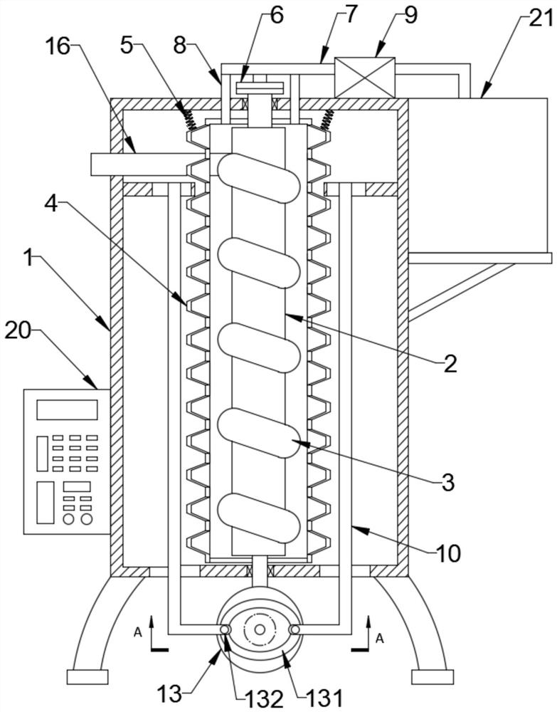
[0046] like figure 1 As shown, a structural diagram of a gas-liquid separator for an oil field provided by an embodiment of the present invention, including a housing 1, also includes:

[0047] A separation assembly, the separation assembly comprising:

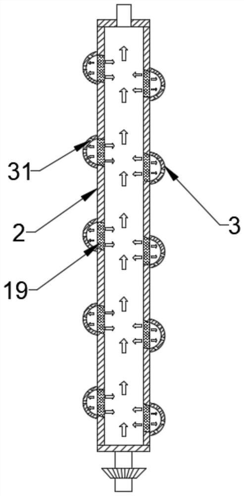
[0048] The spiral tube 3 is installed in the shell 1 and can be rotated relative to the shell 1. The spiral tube 3 is provided with a liquid hole 31, and the spiral tube 3 is used for gas-liquid centrifugal sep...


PUM


Abstract

The invention is applicable to the technical field of petrochemical engineering, and provides a gas-liquid separator for an oil field. The separator comprises a shell, and further comprises: a separation assembly, wherein the separation assembly comprises a spiral pipe, the spiral pipe is mounted in the shell and can rotate relative to the shell, a liquid passing hole is formed in the spiral pipe, and the spiral pipe is used for performing gas-liquid centrifugal separation on a gas-liquid mixture; a multi-fold closed soft sleeve movably mounted in the shell and sleeving the periphery of the spiral pipe, wherein a baffling separation cavity is formed between the spiral pipe and the multi-fold closed soft sleeve; and an extrusion backflow assembly used for extruding the multi-fold closed soft sleeve so as to realize extrusion backflow of liquid obtained after gas-liquid mixture separation and make then the gas-liquid mixture subjected to at least two times of separation action. The gas-liquid separator for the oil field can be used for carrying out extrusion circulation type centrifugal separation and baffling separation on the gas-liquid mixture to realize sufficient separation. Meanwhile, separation products can be effectively absorbed, separation is intelligent, and use is convenient.

Description

technical field [0001] The invention belongs to the related technical field of petrochemical industry, and in particular relates to a gas-liquid separator for oil field. Background technique [0002] In the process of oil extraction in oil fields, the recovery of crude oil is often enhanced by gas injection, CO 2 [0003] Oil flooding technology has many advantages. As an effective oil displacement agent, it has a good oil displacement effect. The reason is that CO is dissolved in crude oil. 2 When , the properties of crude oil will change, which will greatly improve the properties of oil reservoirs and increase the recovery of crude oil. [0004] But using CO 2 In oil flooding, the produced product contains a large amount of gas components, which belongs to foaming crude oil, so it is necessary to separate gas and liquid from the produced product. [0005] In the prior art, when the gas-liquid separation is carried out on the produced material, gravity, centrifugal sepa...

Claims


Application Information

Patent Timeline
IPC IPC(8): B01D45/06B01D45/16B01D53/78
CPCB01D45/16B01D45/06B01D53/78B01D2257/504
Inventor 郭红夏万东齐晓旭刘世恩
Owner 承德石油高等专科学校
Why Eureka
Try Eureka