Cleaning device for part machining

A cleaning device and parts processing technology, applied in the field of parts processing, can solve the problems of uneven cleaning effect, difficult fan, poor air-drying effect, etc.

Active Publication Date: 2021-09-10
南通朗迪机械科技有限公司
View PDF5 Cites 5 Cited by
  • Summary
  • Abstract
  • Description
  • Claims
  • Application Information

AI Technical Summary

Problems solved by technology

[0004] However, in the actual working process, we found that when using this device to clean the parts, the parts are placed on the cleaning tray in a non-moving state, which makes the lower surface of the parts in the process of use. That is, the side that is in contact with the cleaning tray cannot be in contact with the cleaning liquid, resulting in uneven cleaning effect as a whole. Secondly, when the drain pipe of the water storage tank slides down to the outlet pipe, the water in the water storage tank After the sealing cap is automatically opened under the pressure of the pressure, the water in the water storage tank is automatically discharged, and after a little water is discharged, the gravity of the water storage tank has been reduced. It is not reset after the water storage tank is drained, it is also difficult to restore the water storage tank to its original state, and it is difficult to ensure that the follow-up fan continues to be in a higher state, and the effect of air drying is relatively poor

Method used


Image

  • Cleaning device for part machining
  • Cleaning device for part machining
  • Cleaning device for part machining

Examples


Embodiment 1

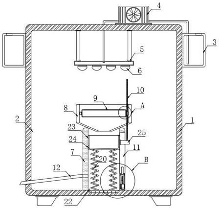
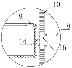
[0029] refer to Figure 1-5 , a cleaning device for parts processing, comprising a housing 1, a plurality of support seats are installed on the lower end of the housing 1 for supporting the housing 1, a cleaning chamber 2 is arranged inside the housing 1, and the inside of the cleaning chamber 2 A support block 7 is installed at the bottom, and a vertical movable groove 22 is provided in the support block 7. The upper end of the support block 7 is fixedly connected with a water collection bucket 8, and a screen frame 9 is arranged in the water collection bucket 8. The upper end surface of the screen frame 9 A net-shaped sliding door is set, through which parts can be put in and taken out, and a transparent airtight door is also installed on the front side of the housing 1, which is convenient for subsequent operation and processing, and the left and right sides of the screen frame 9 are fixedly connected There are rotating rods 14, and each rotating rod 14 is connected to the ...

Embodiment approach

[0030] As an embodiment of the present invention, it also includes a cleaning mechanism. The cleaning mechanism includes an annular water tank 3 fixedly connected to the outer wall of the housing 1. A water pump 4 is installed on the upper end of the housing 1. The water inlet pipe of the water pump 4 extends to the annular water tank. The inner top of 3, the inner top of cleaning chamber 2 are fixedly connected with installation frame 5, and the lower end of installation frame 5 is equipped with a plurality of shower nozzles 6, and the liquid inlet end of a plurality of shower nozzles 6 is all communicated with the outlet pipe of water pump 4.

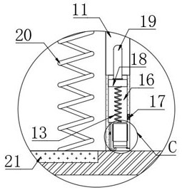
[0031] As an embodiment of the present invention, the inner bottom of the strip-shaped opening 11 is provided with a vertical groove 16, and a trigger mechanism is arranged in the vertical groove 16. The trigger mechanism includes a piston block 18 for sliding up and down in the vertical groove 16, and the piston block The lower end of...

Embodiment 2

[0038] refer to Figure 6-7 The difference between this embodiment and Embodiment 1 is that the piston block 18 is made of conductive material, and the second conductive plate 34 is arranged on the inner walls of both sides of the vertical groove 16, and two hollow holes are arranged obliquely in the cleaning chamber 2. plate 33, the opposite surfaces of the two hollow plates 33 are provided with a plurality of air outlets, the right side of the housing 1 is equipped with a fan 31, the outlet end of the fan 31 is connected with two branch pipes 32, the other ends of the two branch pipes 32 They communicate with the two hollow plates 33 respectively, the positive pole of the external power supply and the second conductive plate 34 on the left are electrically connected by wires, and the negative pole of the external power supply, the fan 31 and the second conductive plate 34 on the right are electrically connected by wires.

[0039] In this embodiment, when the piston block 18 ...


PUM


Abstract

The invention discloses a cleaning device for part machining. The cleaning device for part machining comprises a shell body, a cleaning chamber is arranged in the shell body, a supporting block is installed at the inner bottom of the cleaning chamber, a vertical movable groove is formed in the supporting block, a water collecting hopper is fixedly connected to the upper end of the supporting block, a screen frame is arranged in the water collecting hopper, rotating rods are fixedly connected to the left side and the right side of the screen frame, one end, away from the screen frame, of each rotating rod is rotationally connected with the inner wall of the water collecting hopper, a water collecting box used for sliding up and down is arranged in the movable groove, and the bottom space of the movable groove communicates with the outside through a water outlet pipe. In the cleaning process of the device, the screen frame can be in a rotating state, parts in the screen frame can make uniform contact with cleaning liquid sprayed out of a spray head, the overall cleaning effect is good, in the subsequent air drying process, the screen frame is further in the rotating state, and the air drying effect can be further improved.

Description

technical field [0001] The invention relates to the field of part processing, in particular to a cleaning device for part processing. Background technique [0002] The parts need to be cleaned after the production and processing are completed and before they are packaged and leave the factory. For this, it is generally necessary to use a parts cleaning device to improve the cleaning efficiency; [0003] In this regard, the Chinese invention patent with the application number CN202010739523.3 jointly developed a "parts cleaning device for faucet processing", which includes a box body and two sets of fixing seats, and the two sets of fixing seats are fixedly connected to the inner wall of the box. The inside of the box body is fixedly connected with a fixed frame, and the fixed frame is provided with two groups and symmetrically distributed on both sides of the fixed seat. The fixed frame is fixedly connected with a connecting rod, and the top of the connecting rod is fixedly ...

Claims


Application Information

Patent Timeline
Patent Type & Authority Applications(China)
IPC IPC(8): B08B3/02B08B13/00F26B5/08F26B21/00
CPCB08B3/022B08B13/00F26B5/08F26B21/001
Inventor 吴春飞
Owner 南通朗迪机械科技有限公司
Why Eureka
Try Eureka