Metal punching machining equipment

A technology of punching equipment and hole processing, applied in metal processing equipment, metal processing mechanical parts, drilling/drilling equipment, etc., can solve the problem of waste of coolant

Inactive Publication Date: 2021-09-10
朱荣焕
View PDF0 Cites 2 Cited by
  • Summary
  • Abstract
  • Description
  • Claims
  • Application Information

AI Technical Summary

Problems solved by technology

[0004] Aiming at the deficiencies of the prior art, the present invention provides a metal dri...

Method used


Image

  • Metal punching machining equipment
  • Metal punching machining equipment
  • Metal punching machining equipment

Examples


Embodiment Construction

[0024] The following will clearly and completely describe the technical solutions in the embodiments of the present invention with reference to the accompanying drawings in the embodiments of the present invention. Obviously, the described embodiments are only some, not all, embodiments of the present invention. Based on the embodiments of the present invention, all other embodiments obtained by persons of ordinary skill in the art without making creative efforts belong to the protection scope of the present invention.

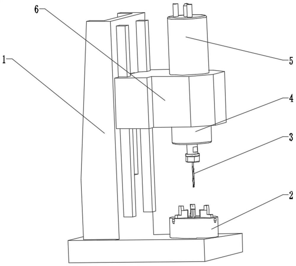
[0025] like Figure 1-6As shown, the present invention provides a technical solution: a metal punching processing equipment, the structure of which includes a main frame 1 of the punching equipment, a lifting device 6 of the clamp 2, and the bottom of the right side of the main frame 1 of the punching equipment is fixedly connected to the bottom of the clamp 2 , a drill bit 3 is installed directly above the fixture 2, the top of the drill bit 3 is fixedly conn...


PUM


Abstract

The invention discloses metal punching machining equipment. The equipment structurally comprises a punching equipment main rack and a clamp lifting device, the bottom of the right side of the punching equipment main rack is fixedly connected with the bottom of a clamp, a drill bit is installed over the clamp, a lubricant releasing device is fixedly connected to the top of the drill bit, the top of the lubricant releasing device is fixedly connected with a driving device, the exteriors of the lubricant releasing device and the driving device are both fixedly connected with a lifting device, the clamp comprises a clamp shell, a high-temperature-resistant clamp head and a fixing frame, the fixing frame is fixedly connected into the clamp shell, and the tail end of the right side of the fixing frame is fixedly connected with the high-temperature-resistant clamp head. The equipment relates to the technical field of metal processing, the high-temperature-resistant clamp head is arranged, so that the situation that due to heat expansion and cold contraction caused by high temperature, a clamp is loosened can be avoided, drilling deviation is prevented, and therefore the drilling accuracy is guaranteed.

Description

technical field [0001] The invention relates to the technical field of metal processing, in particular to a metal drilling processing equipment. Background technique [0002] Generally, the rotation of the drill bit is the main movement, and the axial movement of the drill bit is the feed movement. The drilling machine has a simple structure and relatively low machining accuracy. It can drill through holes and blind holes, replace special tools, expand, countersink, ream or tap. During the machining process, the workpiece does not move, let the tool move, align the center of the tool with the center of the hole, and make the tool rotate (main movement); the existing drilling coolant is opened in advance and closed after drilling. It will cause waste of coolant, so we propose a metal drilling processing equipment. Contents of the invention [0003] (1) Solved technical problems [0004] Aiming at the deficiencies of the prior art, the invention provides a metal drilling ...

Claims


Application Information

Patent Timeline
IPC IPC(8): B23B39/00B23Q11/10
CPCB23B39/00B23Q11/10B23Q11/1038B23Q11/1046
Inventor 朱荣焕
Owner 朱荣焕
Why Eureka
Try Eureka